AD9551/PCBZ Analog Devices Inc, AD9551/PCBZ Datasheet - Page 14
AD9551/PCBZ
Manufacturer Part Number
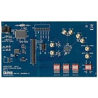
AD9551/PCBZ
Description
BOARD EVAL FOR AD9951
Manufacturer
Analog Devices Inc
Datasheet
1.AD9551PCBZ.pdf
(40 pages)
Specifications of AD9551/PCBZ
Main Purpose
Timing, Clock Generator
Embedded
No
Utilized Ic / Part
AD9551
Primary Attributes
2 Inputs, 2 Outputs, VCO
Secondary Attributes
Graphical User Interface, USB Interface
Silicon Manufacturer
Analog Devices
Application Sub Type
Clock Generator
Kit Application Type
Clock & Timing
Silicon Core Number
AD9551
Kit Contents
Board
Lead Free Status / RoHS Status
Lead free / RoHS Compliant


AD9551
PRESET FREQUENCY RATIOS
The frequency selection pins (A[3:0], B[3:0], and Y[3:0]) allow
the user to hardwire the device for preset input and output divider
values based on the pin logic states. The A[3:0] pins control the
REFA dividers, the B[3:0] pins control the REFB dividers, and
the Y[3:0] pins control the feedback and output dividers. The
pins decode ground or open connections as Logic 0 or Logic 1,
respectively. To override the preset divider settings, use the serial
I/O port to program the desired divider values.
Table 13 lists the input divider values based on the logic state of
the frequency selection pins. The table headings are as follows:
•
•
Table 13. Preset Input Settings
A[3:0], B[3:0]
0000
0001
0010
0011
0100
0101
0110
0111
1000
1001
1010
1011
1100
1101
1110
1111
1
2
Assumes the use of a 26 MHz external crystal.
If all four A[3:0] pins or all four B[3:0] pins are Logic 1, the 19.44 MHz mode is in effect.
A[3:0], B[3:0]. The logic state of the A[3:0] or B[3:0] pins.
N
the REFB input divider (N
2
A
, N
B
. The integer part of the REFA input divider (N
N
23
24
24
24
24
25
25
25
25
25
25
26
27
27
26
A
, N
B
).
B
MOD
130,000
130,000
154,050
130,000
166,400
104,000
198,016
154,700
154,050
182,000
153,400
197,184
146,900
198,016
197,184
A
A
, MOD
) or
Rev. B | Page 14 of 40
B
•
•
•
The divider settings shown in Table 13 cause the frequency at the
reference input of the output PLL’s PFD (f
26 MHz when using the indicated input reference frequency,
f
19.44 MHz mode
REF
A
MOD
SDM (MOD
FRAC
divider SDM (FRAC
(FRAC
f
REFB input (f
or f
REF
FRAC
110,800
−120,000
−114,594
45,200
96,400
−44,625
−42,891
41,820
74,970
93,000
108,120
67,998
83,612
−161,755
−115,995
A
REF
, f
A
A
REF
B
, MOD
B
, FRAC
, assuming the use of a 26 MHz external crystal.
).
A
B
, FRAC
. The frequency of the REFA input (f
A
) or the REFB input divider SDM (MOD
REF
B
B
. The modulus of the REFA input divider
. The fractional part of the REFA input
B
B
).
A
) or the REFB input divider SDM
f
622.08
625
622
622
625
622
622
625
622
625
622
10518
10518
10518
10518
REF
IF
) to operate at exactly
16
16
16
16
A
.
( )
( )
.
, f
.
.
.
( ) ( )
.
08
.
08
.
08
.
08
08
.
75
08
75
66
64
75
15
14
255
237
75
REF
( )
( )
( )
( )
( )
( )
≡
( )
( )
( )
66
64
255
237
255
236
≡
239
238
≈
255
238
239
237
255
238
255
237
253
226
B
×
657
644
669
(MHz)
≡
66
64
≈
≈
≈
≈
≈
≈
≈
≈
641
REF
.
421875
707
.
.
672
696
704
627
660
669
53125
666
64
≈
A
.
693
) or the
1
52
.
.
.
.
.
.
35
.
16
.
40
38
33
18
33
51
.
B
48
).
Related parts for AD9551/PCBZ
Image
Part Number
Description
Manufacturer
Datasheet
Request
R


Part Number:
Description:
±1.7g Dual-Axis IMEMS Accelerometer Evaluation Board
Manufacturer:
Analog Devices Inc
Datasheet:

Part Number:
Description:
Inertial Sensor Evaluation System
Manufacturer:
Analog Devices Inc
Datasheet:
Part Number:
Description:
Manufacturer:
Analog Devices Inc
Datasheet:
Part Number:
Description:
Manufacturer:
Analog Devices Inc
Datasheet:
Part Number:
Description:
Manufacturer:
Analog Devices Inc
Datasheet:
Part Number:
Description:
Manufacturer:
Analog Devices Inc
Datasheet:
Part Number:
Description:
Manufacturer:
Analog Devices Inc
Datasheet:
Part Number:
Description:
Manufacturer:
Analog Devices Inc
Datasheet:
Part Number:
Description:
Manufacturer:
Analog Devices Inc
Datasheet:
Part Number:
Description:
Manufacturer:
Analog Devices Inc
Datasheet:
Part Number:
Description:
Manufacturer:
Analog Devices Inc
Datasheet:
Part Number:
Description:
Manufacturer:
Analog Devices Inc
Datasheet: