AD9551/PCBZ Analog Devices Inc, AD9551/PCBZ Datasheet - Page 15
AD9551/PCBZ
Manufacturer Part Number
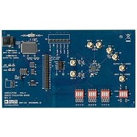
AD9551/PCBZ
Description
BOARD EVAL FOR AD9951
Manufacturer
Analog Devices Inc
Datasheet
1.AD9551PCBZ.pdf
(40 pages)
Specifications of AD9551/PCBZ
Main Purpose
Timing, Clock Generator
Embedded
No
Utilized Ic / Part
AD9551
Primary Attributes
2 Inputs, 2 Outputs, VCO
Secondary Attributes
Graphical User Interface, USB Interface
Silicon Manufacturer
Analog Devices
Application Sub Type
Clock Generator
Kit Application Type
Clock & Timing
Silicon Core Number
AD9551
Kit Contents
Board
Lead Free Status / RoHS Status
Lead free / RoHS Compliant


The Y[3:0] pins select the divider values for the feedback path of
the output PLL, as well as for the OUT1 dividers, P
OUT2 divider, P
med using the serial port. Table 14 lists the feedback and output
divider values based on the logic state of the Y[3:0] frequency
selection pins. The table headings are as follows:
•
•
•
•
•
•
Table 14. Preset Output Settings
Y[3:0]
0000
0001
0010
0011
0100
0101
0110
0111
1000
1001
1010
1011
1100
1101
1110
1111
Y[3:0]. The logic state of the Y[3:0] pins.
N. The integer part of the feedback divider.
MOD. The modulus of the feedback SDM.
FRAC. The fractional part of the feedback SDM.
P
f
OUT1
0
, P
. The frequency of the OUT1 output.
1
. The P
2
0
, defaults to unity unless otherwise program-
and P
N
143
144
144
148
148
151
152
153
154
154
155
133
133
135
136
149
1
divider values.
MOD
520,000
520,000
308,100
520,000
465,920
520,000
465,920
465,920
328,640
460,096
490,880
328,640
470,080
349,440
394,368
520,000
0
and P
1
. The
Rev. B | Page 15 of 40
FRAC
289,600
120,000
236,736
22,400
343,840
370,625
163,160
377,856
151,168
245,216
56,192
119,005
433,856
159,975
11,577
280,000
The divider settings shown in Table 14 produce the indicated
frequency at OUT1 when the frequency at the reference input
of the output PLL’s PFD (f
When operating in the 19.44 MHz mode, the N, MOD, and FRAC
values may be different from those shown in Table 14, but the
f
mode relies on a crystal with a resonant frequency other than 26
MHz (see the 19.44 MHz Mode section in the Operating Modes
portion of the Theory of Operation section).
OUT1
values remain the same. The reason is that the 19.44 MHz
P
6/1
6/1
6/1
6/1
6/1
6/1
6/1
6/1
6/1
6/1
6/1
5/1
5/1
5/1
5/1
5/1
0
, P
1
IF
) is exactly 26 MHz.
f
622.08
625
622
622
622
622
622
625
622
625
10518
10518
625
10518
10518
622
OUT1
16
16
16
16
.
.
.
.
.
( )
( )( )
.
( )
08
08
.
.
08
.
.
.
08
08
08
75
75
75
75
(MHz)
08
15
14
255
237
66
64
( )
( )
( )
( )
( )
≡
( )
( )
( )
( )
255
236
255
238
( )
66
64
239
238
237
255
237
239
237
255
238
255
253
226
≈
≡
10
657
8
66
64
669
AD9551
644
≡
≈
≈
≈
≈
≈
≈
≈
≈
≡
≈
641
.
672
421875
704
669
707
660
666
627
696
777
.
.
693
64
53125
.
.
52
16
.
.
.
.
.
.
38
.
33
18
51
35
40
33
.
6 .
48
Related parts for AD9551/PCBZ
Image
Part Number
Description
Manufacturer
Datasheet
Request
R


Part Number:
Description:
±1.7g Dual-Axis IMEMS Accelerometer Evaluation Board
Manufacturer:
Analog Devices Inc
Datasheet:

Part Number:
Description:
Inertial Sensor Evaluation System
Manufacturer:
Analog Devices Inc
Datasheet:
Part Number:
Description:
Manufacturer:
Analog Devices Inc
Datasheet:
Part Number:
Description:
Manufacturer:
Analog Devices Inc
Datasheet:
Part Number:
Description:
Manufacturer:
Analog Devices Inc
Datasheet:
Part Number:
Description:
Manufacturer:
Analog Devices Inc
Datasheet:
Part Number:
Description:
Manufacturer:
Analog Devices Inc
Datasheet:
Part Number:
Description:
Manufacturer:
Analog Devices Inc
Datasheet:
Part Number:
Description:
Manufacturer:
Analog Devices Inc
Datasheet:
Part Number:
Description:
Manufacturer:
Analog Devices Inc
Datasheet:
Part Number:
Description:
Manufacturer:
Analog Devices Inc
Datasheet:
Part Number:
Description:
Manufacturer:
Analog Devices Inc
Datasheet: