AD9551/PCBZ Analog Devices Inc, AD9551/PCBZ Datasheet - Page 17
AD9551/PCBZ
Manufacturer Part Number
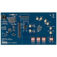
AD9551/PCBZ
Description
BOARD EVAL FOR AD9951
Manufacturer
Analog Devices Inc
Datasheet
1.AD9551PCBZ.pdf
(40 pages)
Specifications of AD9551/PCBZ
Main Purpose
Timing, Clock Generator
Embedded
No
Utilized Ic / Part
AD9551
Primary Attributes
2 Inputs, 2 Outputs, VCO
Secondary Attributes
Graphical User Interface, USB Interface
Silicon Manufacturer
Analog Devices
Application Sub Type
Clock Generator
Kit Application Type
Clock & Timing
Silicon Core Number
AD9551
Kit Contents
Board
Lead Free Status / RoHS Status
Lead free / RoHS Compliant


Synchronization/Switchover Control
Figure 19, which is a block diagram of the hitless reference switch-
over circuit, shows that reference synchronization occurs after
the input reference dividers. The synchronization and switchover
functionality relies on the reference monitor logic to control the
operation of the three delay-locked loops (DLLs). The delay blocks
of the three DLLs are identical, so that they exhibit the same time
delay for a given delay value setting.
Note that the DCXO must be operational for the synchroniza-
tion and switchover control to operate.
Both the REFA and REFB paths have a dedicated DLL (DLL A
and DLL B, respectively). DLL A and DLL B are each capable of
operating in either an open-loop or closed-loop mode under the
direction of the reference monitor status signals. When the
reference monitor selects one of the references as the active
reference, the DLL associated with the active reference operates
in open-loop mode. While in open-loop mode, the DLL delays
the active reference by a constant time interval based on a fixed
delay value. As long as one of the references is the active refer-
ence, the other reference is, by default, the alternate reference.
The DLL associated with the alternate reference operates in closed-
loop mode. While in closed-loop mode, the DLL automatically
adjusts its delay so that the rising edge of the delayed alternate
reference is edge-aligned with the rising edge of the delayed
active reference.
REFB, REFB
REFA, REFA
÷
÷
REFERENCE
MONITOR
1
0
A/B
Figure 19. Synchronization Block Diagram
÷
2
1
DELAY
0
DELAY
Rev. B | Page 17 of 40
0
1
LOCKED
A/B
ACC
ACC
A/B
REF.
DLL
HOLD A
HOLD B
DLL B
DLL A
When the reference monitor selects one of the references as the
active reference, it switches the output mux to select the output of
the DLL associated with the active reference and, simultaneously,
routes the active reference to the reference DLL. The reference
DLL automatically measures the period of the active reference
(with approximately 250 ps accuracy). When the reference DLL
locks, the value of its delay setting (N) represents one period of
the active reference. Upon acquiring lock, the reference DLL
captures N and divides it by two (N/2 corresponds to a delay value
that represents a half-cycle of the active reference). Both DLL A and
DLL B have access to the N/2 value generated by the reference DLL.
The following paragraphs describe the typical sequence of events
resulting from a device reset, power-up, or return from hold-
over mode.
Active Reference and Alternate Reference
The reference monitor continuously checks for the presence of the
divided REFA and/or REFB signals. If both signals are avail-able,
the device arbitrarily selects one of them as the active reference,
making the other the alternate reference. If only one of the
references is available, it becomes the active reference, making the
other the alternate reference (if it ever becomes available). In
either case, the following two events occur:
•
•
P
D
P
D
F
F
D Q
The output mux selects the output of the active DLL as the
source to the input PLL.
The input mux selects the active reference as the source to
the reference DLL.
N/2
1
0
A/B
INPUT
DCXO
PLL
TO
OUTPUT
PLL
AD9551
Related parts for AD9551/PCBZ
Image
Part Number
Description
Manufacturer
Datasheet
Request
R


Part Number:
Description:
±1.7g Dual-Axis IMEMS Accelerometer Evaluation Board
Manufacturer:
Analog Devices Inc
Datasheet:

Part Number:
Description:
Inertial Sensor Evaluation System
Manufacturer:
Analog Devices Inc
Datasheet:
Part Number:
Description:
Manufacturer:
Analog Devices Inc
Datasheet:
Part Number:
Description:
Manufacturer:
Analog Devices Inc
Datasheet:
Part Number:
Description:
Manufacturer:
Analog Devices Inc
Datasheet:
Part Number:
Description:
Manufacturer:
Analog Devices Inc
Datasheet:
Part Number:
Description:
Manufacturer:
Analog Devices Inc
Datasheet:
Part Number:
Description:
Manufacturer:
Analog Devices Inc
Datasheet:
Part Number:
Description:
Manufacturer:
Analog Devices Inc
Datasheet:
Part Number:
Description:
Manufacturer:
Analog Devices Inc
Datasheet:
Part Number:
Description:
Manufacturer:
Analog Devices Inc
Datasheet:
Part Number:
Description:
Manufacturer:
Analog Devices Inc
Datasheet: