AD9551/PCBZ Analog Devices Inc, AD9551/PCBZ Datasheet - Page 23
AD9551/PCBZ
Manufacturer Part Number
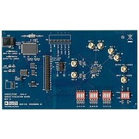
AD9551/PCBZ
Description
BOARD EVAL FOR AD9951
Manufacturer
Analog Devices Inc
Datasheet
1.AD9551PCBZ.pdf
(40 pages)
Specifications of AD9551/PCBZ
Main Purpose
Timing, Clock Generator
Embedded
No
Utilized Ic / Part
AD9551
Primary Attributes
2 Inputs, 2 Outputs, VCO
Secondary Attributes
Graphical User Interface, USB Interface
Silicon Manufacturer
Analog Devices
Application Sub Type
Clock Generator
Kit Application Type
Clock & Timing
Silicon Core Number
AD9551
Kit Contents
Board
Lead Free Status / RoHS Status
Lead free / RoHS Compliant


4.
Determine the feedback divider values for the output PLL.
Repeat this step for each ODF when multiple ODFs exist
(for example, 35, 36, and 40, in the case of Table 17).
To calculate the feedback divider values for a given ODF, use
the following equation:
Note that the left side of the equation contains variables
with known quantities. Furthermore, the values are neces-
sarily rational, so the left side is expressible as a ratio of two
integers, X and Y. The following is an example equation:
In the context of the AD9551, X/Y is always an improper
fraction. Therefore, it is expressible as the sum of an integer,
N, and the proper fraction, R/Y (R and Y are integers).
Therefore, the example yields N = 148, Y = 1664, and R =
1228. To arrive at this result, use long division to convert the
improper fraction, X/Y, to an integer (N) and a proper fraction
(R/Y). Note that dividing Y into X by means of long division
yields an integer, N, and a remainder, R. The proper fraction
has a numerator (R, the remainder) and a denominator (Y,
the divisor), as follows:
It is imperative to use long division to obtain the correct
results. Avoid the use of a calculator or math program
because these do not always yield correct results due to
internal rounding and/or truncation. Some calculators or
math programs may be up to the task if they can handle very
large integer operations, but such are not common.
In the example, N = 148 and R/Y = 1228/1664, which reduces
to R/Y = 307/416. These values of N, R, and Y constitute
the fol-lowing respective feedback divider values: N = 148,
FRAC = 307, and MOD = 416.
The only caveat is that N and MOD must meet the constraints
given in the Output/Input Frequency Relationship section.
⎛
⎜
⎜
⎝
⎛
⎜
⎜
⎜
⎜
⎝
247
X
Y
625
1664
f
OUT1
f
=
IF
,
500
26
⎡ 66
⎢
⎣
N
64
⎞
⎟
⎟
⎠
+
×
=
⎤
⎥
⎦
Y
R
ODF
⎞
⎟
⎟
⎟
⎟
⎠
N +
×
Y X
Figure 23. Example Long Division
–NY
6
Y
R
N
R
=
=
Y
X
625
26
(
66
(
64
)(
Y
X
)
) 6
= N +
=
247
1664
Y
R
,
500
=
Y
X
Rev. B | Page 23 of 40
5.
In the example, FRAC is nonzero, so the division value is
an integer plus the fractional component, FRAC/MOD. This
implies that the feedback SDM is necessary as part of the feed-
back divider. If FRAC = 0, the feedback division factor is an
integer and the SDM is not required (it can be bypassed).
Although the feedback divider values obtained in this way
provide the proper feedback divide ratio to synthesize the
exact output frequency, they may not yield optimal jitter
performance at the final output. One reason for this is that
the value of MOD defines the period of the SDM, which has
a direct impact on the spurious output of the SDM. Spe-
cifically, the SDM spectrum has MOD at evenly spaced
spurs between dc and f
(Δf) of the spurs associated with the feedback SDM is
Because the SDM is in the feedback path of the output PLL,
these spurs appear in the output signal as spurious compo-
nents offset by Δf from f
produces relatively large spurs, with relatively large frequency
offsets from f
smaller spurs but more closely spaced to f
value of MOD has a direct impact on the spurious content
(that is, jitter) at OUT1.
Generally, the largest possible MOD value yields the smallest
spurs. Thus, it is desirable to scale MOD and FRAC by the
integer part of 2
previously. In the example, the value of MOD is 416, yielding
a scale factor of 2520 (the integer part of 2
factor of 2520 leads to FRAC = 307 × 2520 = 773,640, and
MOD = 416 × 2520 = 1,048,320.
However, these FRAC and MOD values are different from
those that appear in Table 14 (Y[3:0] = 0100). The reason is
that a scale factor of 1120 (instead of 2520) was found to yield
the most accept-able overall performance. A scale factor of
1120 results in the following Table 14 values: FRAC =
343,840 and MOD = 465,920.
Determine the values of the REFA (or REFB) input dividers.
To calculate the feedback divider values, use the following
equation:
Note that the left side of the equation contains variables
with known quantities. Furthermore, the values are neces-
sarily rational, so the left side is expressible as a ratio of two
integers, X and Y. The following is an example equation:
Δ
622
f
f
REF
f
IF
=
.
08
MOD
26
=
⎛
⎜
⎝
f
IF
239
237
X
Y
⎞
⎟
⎠
OUT1
=
20
100
, whereas a large MOD value produces
62208
divided by the value of MOD obtained
(
26
IF
)(
(
OUT1
239
. Thus, the spectral sepa-ration
237
. Therefore, a small MOD value
)
)
=
14
616
,
867
,
200
,
712
20
OUT1
/416). A scale
=
. Clearly, the
Y
X
AD9551
Related parts for AD9551/PCBZ
Image
Part Number
Description
Manufacturer
Datasheet
Request
R


Part Number:
Description:
±1.7g Dual-Axis IMEMS Accelerometer Evaluation Board
Manufacturer:
Analog Devices Inc
Datasheet:

Part Number:
Description:
Inertial Sensor Evaluation System
Manufacturer:
Analog Devices Inc
Datasheet:
Part Number:
Description:
Manufacturer:
Analog Devices Inc
Datasheet:
Part Number:
Description:
Manufacturer:
Analog Devices Inc
Datasheet:
Part Number:
Description:
Manufacturer:
Analog Devices Inc
Datasheet:
Part Number:
Description:
Manufacturer:
Analog Devices Inc
Datasheet:
Part Number:
Description:
Manufacturer:
Analog Devices Inc
Datasheet:
Part Number:
Description:
Manufacturer:
Analog Devices Inc
Datasheet:
Part Number:
Description:
Manufacturer:
Analog Devices Inc
Datasheet:
Part Number:
Description:
Manufacturer:
Analog Devices Inc
Datasheet:
Part Number:
Description:
Manufacturer:
Analog Devices Inc
Datasheet:
Part Number:
Description:
Manufacturer:
Analog Devices Inc
Datasheet: