AD9551/PCBZ Analog Devices Inc, AD9551/PCBZ Datasheet - Page 38
AD9551/PCBZ
Manufacturer Part Number
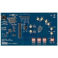
AD9551/PCBZ
Description
BOARD EVAL FOR AD9951
Manufacturer
Analog Devices Inc
Datasheet
1.AD9551PCBZ.pdf
(40 pages)
Specifications of AD9551/PCBZ
Main Purpose
Timing, Clock Generator
Embedded
No
Utilized Ic / Part
AD9551
Primary Attributes
2 Inputs, 2 Outputs, VCO
Secondary Attributes
Graphical User Interface, USB Interface
Silicon Manufacturer
Analog Devices
Application Sub Type
Clock Generator
Kit Application Type
Clock & Timing
Silicon Core Number
AD9551
Kit Contents
Board
Lead Free Status / RoHS Status
Lead free / RoHS Compliant


AD9551
OUT1 Driver Control (Register 0x32)
Table 33.
Address
0x32
Input PLL Control (Register 0x33)
Table 34.
Address
0x33
Bit
7
6
[5:4]
[3:0]
Bit
7
6
[5:3]
[2:1]
0
Bit Name
Loop filter sample rate control
Select 2× frequency divider
Select crystal frequency
Unused
Bit Name
OUT1 drive strength
OUT1 power-down
OUT1 mode control
OUT1 CMOS polarity
Enable SPI control of OUT1
driver control
Description
Controls the output drive capability of the OUT1 driver.
0 = weak.
1 = strong (default).
Controls power-down functionality of the OUT1 driver.
0 = OUT1 active (default).
1 = OUT1 powered down.
OUT1 driver mode selection.
000 = CMOS, both pins active.
001 = CMOS, positive pin active, negative pin tristate.
010 = CMOS, positive pin tristate, negative pin active.
011 = CMOS, both pins tristate.
100 = LVDS.
101 = LVPECL (default).
110 = not used.
111 = not used.
Selects the polarity of the OUT1 pins in CMOS mode.
00 = positive pin logic is true = 1, false = 0/negative pin logic is true = 0, false = 1 (default).
01 = positive pin logic is true = 1, false = 0/negative pin logic is true = 1, false = 0.
10 = positive pin logic is true = 0, false = 1/negative pin logic is true = 0, false = 1.
11 = positive pin logic is true = 0, false = 1/negative pin logic is true = 1, false = 0.
These bits are ineffective unless Bits[5:3] select CMOS mode.
Controls OUT1 driver functionality.
0 = OUT1 is LVDS or LVPECL, per the OUTSEL pin (Pin 16) (default).
1 = OUT1 functionality defined by Bits[7:1].
Description
Select/bypass 8× clock divider to the digital loop filter.
0 = selected (default).
1 = bypassed.
Select/bypass the 2× frequency divider.
0 = bypassed (default).
1 = selected.
Note that this bit is not functional in 19.44 MHz mode.
Select the crystal frequency for 19.44 MHz mode.
00 = 52.000 MHz (default).
01 = 50.000 MHz.
10 = 49.860 MHz.
11 = 49.152 MHz.
Note that these bits are functional only in 19.44 MHz mode.
Unused.
Rev. B | Page 38 of 40
Related parts for AD9551/PCBZ
Image
Part Number
Description
Manufacturer
Datasheet
Request
R


Part Number:
Description:
±1.7g Dual-Axis IMEMS Accelerometer Evaluation Board
Manufacturer:
Analog Devices Inc
Datasheet:

Part Number:
Description:
Inertial Sensor Evaluation System
Manufacturer:
Analog Devices Inc
Datasheet:
Part Number:
Description:
Manufacturer:
Analog Devices Inc
Datasheet:
Part Number:
Description:
Manufacturer:
Analog Devices Inc
Datasheet:
Part Number:
Description:
Manufacturer:
Analog Devices Inc
Datasheet:
Part Number:
Description:
Manufacturer:
Analog Devices Inc
Datasheet:
Part Number:
Description:
Manufacturer:
Analog Devices Inc
Datasheet:
Part Number:
Description:
Manufacturer:
Analog Devices Inc
Datasheet:
Part Number:
Description:
Manufacturer:
Analog Devices Inc
Datasheet:
Part Number:
Description:
Manufacturer:
Analog Devices Inc
Datasheet:
Part Number:
Description:
Manufacturer:
Analog Devices Inc
Datasheet:
Part Number:
Description:
Manufacturer:
Analog Devices Inc
Datasheet: