ADNK-5003 Avago Technologies US Inc., ADNK-5003 Datasheet

KIT REF DES OPT MOUSE ADNS-5000

ADNK-5003

Manufacturer Part Number
ADNK-5003
Description
KIT REF DES OPT MOUSE ADNS-5000
Manufacturer
Avago Technologies US Inc.
Datasheet

Specifications of ADNK-5003

Main Purpose
Reference Design, Optical Mouse
Utilized Ic / Part
ADNS-5000
Product
Tools & Accessories
Lead Free Status / RoHS Status
Lead free / RoHS Compliant
Secondary Attributes
-
Embedded
-
Primary Attributes
-
Lead Free Status / Rohs Status
Lead free / RoHS Compliant
ADNK-5003
Optical Mouse Designer’s Kit
Design Guide
Introduction
The Universal Serial Bus (USB) is an industry standard se-
rial interface between a computer and peripherals such
as a mouse, joystick, keyboard, etc. This design guide
describes how a cost-effective USB optical mouse can be
built using the Avago Technologies ADNS-5000 optical
sensor. The document starts with the basic operations
of a computer mouse peripheral followed by an intro-
duction to the Avago Technologies ADNS-5000 Optical
Navigation Sensor. A schematic of the ADNS-5000 optical
sensor and buttons of a standard mouse can be found in
Appendix A. The ADNS-5000 data sheet is available from
the Avago Technologies web site at www.avagotech.com.
USB documentation can be found at the USB Implement-
ers Forum web site at www.usb.org.
The ADNS-5000 navigation sensor along with the ADNS-
5100 round lens or ADNS-5100-001 trim lens, ADNS-5200
clip and HLMP-ED80 LED form a complete and compact
mouse tracking system. There are no moving parts, which
means high reliability and less maintenance for the end
user. In addition, precision optical alignment is not re-
quired, facilitating high volume assembly.
Optical Mouse Basics
The optical mouse measures changes in position by opti-
cally acquiring sequential surface images (frames), and
mathematically determining the direction and magni-
tude of movement. The Z-wheel movement is done in the
traditional method by decoding the quadrature signal
generated by optical sensors. This design guide shows
how to connect to and manage a standard configuration
of mouse hardware, as well as handle the USB protocols
as a standard way of reporting mouse movement and
button presses to the PC.
Optical Navigation Sensor
Avago Technologies ADNS-5000 optical sensor is used in
this reference design as the primary navigation engine.
This Optical Navigation Technology contains an Image
Acquisition System, a Digital Signal Processor and USB
stream output.
The IAS acquires microscopic surface images via the lens
and illumination system provided by the ADNS-5100,
ADNS-5200, and HLMP-ED80-XX000. These images are
processed by the DSP to determine the direction and
distance of motion. The DSP generates the ∆x and ∆y
relative displacement values which are converted to USB
motion data.
Mouse Z-Wheel
The motion of Z-wheel is detected using the traditional
method by decoding the quadrature signal generated by
optical sensors:
For mechanical Z-wheels the following must be imple-
mented.
1. Use a rotary switch equivalent to the Panasonic part
2. Solder the rotary switch into the PCB such that the
3. Connect the “A” terminal of the rotary switch to “ZA”
As shown in Figure 2 below, traveling along the quadra-
ture signal to the right produces a unique set of state
transitions, and traveling to the left produces another set
of unique state transitions.
EVQVX at http://industrial.panasonic.com/www-
data/pdf/ATC0000/ATC0000CE20.pdf (The key point
is stable “A” switch state in all detent positions).
common pin is closest to the cable end of the mouse.
(Metal plate faces to left)
and the “B” terminal to “ZB”. ZA MUST be connected
to “Signal A” in Figure 2 where the z-wheel detents are
mechanically stable.

Related parts for ADNK-5003

ADNK-5003 Summary of contents

Page 1

... ADNK-5003 Optical Mouse Designer’s Kit Design Guide Introduction The Universal Serial Bus (USB industry standard se- rial interface between a computer and peripherals such as a mouse, joystick, keyboard, etc. This design guide describes how a cost-effective USB optical mouse can be built using the Avago Technologies ADNS-5000 optical sensor ...

Page 2

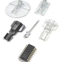
... B4 11 Figure 2. Optics Quadrature Signal Generation Some details on ADNK-5003 The ADNK-5003 reference design mouse unit allows us- ers to evaluate the performance of the Optical Tracking Engine (sensor, lens, LED assembly clip, LED) over a USB protocol. This kit also enables users to understand the recommended mechanical assembly. (See Appendix C ...

Page 3

... The ADNK-5003 comprises of the plastic mouse casing, printed circuit board (PCB), lens, buttons, and USB cable. (See Figure 3) Unscrewing the one screw located at the base of the unit can open the ADNK-5003 unit. Lifting and pulling the PCB out of the base plate can further disassemble the mouse unit. ...

Page 4

... See Appendix D for details. Reference Design Documentation – Gerber File The Gerber File presents detailed schematics used in ADNK-5003 in PCB layout form. See Appendix C for more details. Table 1. USB Strap (Jumper) Table The PID/string strap matrix is the following: ...

Page 5

... USB D− USB D+ Vdd Mechanical 4 Z_wheel ZB OPT 3.3V 12 Figure A1. Circuit-level block diagram for ADNK-5003 designer’s kit optical mouse using the Avago Technologies ADNS-5000 optical mouse 5 Vdd 5V C1, C2 0.1uF C4 = 4.7uF 3.3 uF VDD5 GND 8 Vdd 5V LED_GND 5 R1 NAV LED 6 OSC IN ...

Page 6

Appendix B: Bill of Materials for Components Shown on schematic Part Type Designator 59R R8 750R 1.5k R9 10k R2 10k R4 22k R5 22k R6 100nF C4 100nF C3 100nF C5 3.3uF/16V C1 4.7uF/16V ...

Page 7

Appendix C: PCB Layout Figure C1. PCB Schematic (Bottom Layer) Figure C2. PCB Schematic (Top Overlay) 7 ...

Page 8

... Trim Lens Plate ADNS-5200 LED Assembly Clip HLMP-ED80-XX000 LED ADNK-5003 CD Includes Documentation and Support Files for ADNK-5003 Documentation a. ADNS-5000 Optical Mouse Sensor Data Sheet b. ADNS-5100 Round Lens and ADNS-5100-001 Trim Lens Data Sheet c. ADNS-5200 LED Assembly Clip d. HLMP-ED80-XX000 LED Data Sheet Hardware Support Files a ...

Related keywords