AD9959/PCBZ Analog Devices Inc, AD9959/PCBZ Datasheet - Page 5
AD9959/PCBZ
Manufacturer Part Number
AD9959/PCBZ
Description
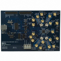
BOARD EVALUATION FOR AD9959
Manufacturer
Analog Devices Inc
Datasheet
1.AD9959PCBZ.pdf
(28 pages)
Specifications of AD9959/PCBZ
Design Resources
Phase Coherent FSK Modulator (CN0186)
Main Purpose
Timing, Direct Digital Synthesis (DDS)
Embedded
No
Utilized Ic / Part
AD9959
Primary Attributes
10-Bit DAC, 32-Bit Tuning Word Width
Secondary Attributes
4 Channels
Silicon Core Number
AD9959
Application Sub Type
Frequency Synthesizer
Kit Contents
Board, AD9959 / PCB Installation Software
Silicon Manufacturer
Analog Devices
Lead Free Status / RoHS Status
Lead free / RoHS Compliant
Other names
AD9959/PCB
AD9959/PCB
Q2548077
AD9959/PCB
Q2548077


EVALUATION BOARD SOFTWARE
INSTALLING THE SOFTWARE
Follow these steps to install the AD9959 evaluation software:
1.
2.
3.
4.
CONFIGURING THE EVALUATION BOARD
Once the software has been successfully installed onto your PC,
the next step is to interface the AD9959 evaluation software to
the AD9959 evaluation board via the USB Port (see Figure 2).
In order for the evaluation board and software to communicate
properly, drivers must be loaded onto your PC system. The
following instructions explain how to install these drivers on
your PC system.
Windows 98/ME/2000 Users
1.
2.
3.
Log into your PC system with administrative privileges;
this is an essential requirement in successfully installing
the AD9959 evaluation software.
Uninstall any previous versions of the AD9959 evaluation
software from your PC system.
Insert the AD9959 evaluation software CD into your
CD-ROM drive. It is important not to connect the
AD9959 evaluation board to the computer until the
AD9959 evaluation software has been successfully
installed. Refer to the Readme.txt file located in the
Software folder before proceeding with the installation
of the AD9959 evaluation software.
Run the setup.exe file located in the Software folder and
follow the AD9959 evaluation software’s on-screen
installation instructions.
Power up the AD9959 evaluation board (see Table 2).
Connect the evaluation board to the computer using a USB
cable via the USB port; the VBUS LED (CR1 on AD9959
evaluation board) illuminates.
When the USB cable is connected, this window appears
and then disappears (Figure 3).
Figure 3.
Rev. 0 | Page 5 of 28
4.
5.
6.
After the window has disappeared, the USB Status LED (CR2
on AD9959 evaluation board) flashes, which indicates that the
evaluation board is connected properly.
Then, this window (Figure 4) also appears and disappears.
If you are using Windows 2000, click Finish if you see this
window (Figure 5).
Next, the window in Figure 6 appears.
Figure 4.
Figure 5.
Figure 6.
AD9959/PCB
Related parts for AD9959/PCBZ
Image
Part Number
Description
Manufacturer
Datasheet
Request
R


Part Number:
Description:
±1.7g Dual-Axis IMEMS Accelerometer Evaluation Board
Manufacturer:
Analog Devices Inc
Datasheet:

Part Number:
Description:
Inertial Sensor Evaluation System
Manufacturer:
Analog Devices Inc
Datasheet:
Part Number:
Description:
Manufacturer:
Analog Devices Inc
Datasheet:
Part Number:
Description:
Manufacturer:
Analog Devices Inc
Datasheet:
Part Number:
Description:
Manufacturer:
Analog Devices Inc
Datasheet:
Part Number:
Description:
Manufacturer:
Analog Devices Inc
Datasheet:
Part Number:
Description:
Manufacturer:
Analog Devices Inc
Datasheet:
Part Number:
Description:
Manufacturer:
Analog Devices Inc
Datasheet:
Part Number:
Description:
Manufacturer:
Analog Devices Inc
Datasheet:
Part Number:
Description:
Manufacturer:
Analog Devices Inc
Datasheet:
Part Number:
Description:
Manufacturer:
Analog Devices Inc
Datasheet:
Part Number:
Description:
Manufacturer:
Analog Devices Inc
Datasheet: