STEVAL-PCC004V1 STMicroelectronics, STEVAL-PCC004V1 Datasheet
STEVAL-PCC004V1
Specifications of STEVAL-PCC004V1
STEVAL-PCC004V1


Related parts for STEVAL-PCC004V1


STEVAL-PCC004V1 Summary of contents
Page 1
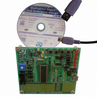
... Reference: – STEVAL-PCC003V1: low-speed USB evaluation board based on the STUSB03 transceiver and ST72F63B – STEVAL-PCC004V1: low-speed USB evaluation board based on the STUSB02E transceiver and ST72F63B Figure 1. USB low-speed evaluation board - STEVAL-PCC003V1 June 2008 STUSB02E and STUSB03 low-speed ...
Page 2
Contents Contents 1 Getting started . . . . . . . . . . . . . . . . . . . . . . . . . . . . . . . . . . . ...
Page 3
UM0529 6.1.1 6.1.2 6.2 USB suspend . . . . . . . . . . . . . . . . . . . . . . . . . . . . . . . . . . ...
Page 4
... List of figures List of figures Figure 1. USB low-speed evaluation board - STEVAL-PCC003V1 . . . . . . . . . . . . . . . . . . . . . . . . . . . 1 Figure 2. STUSB02E/STUSB03E- low-speed evaluation board enumeration in GUI . . . . . . . . . . . . . 7 Figure 3. STUSB02E/ STUSB03 evaluation board block diagram . . . . . . . . . . . . . . . . . . . . . . . . . . . 8 Figure 4. STUSB02E/STUSB03E evaluation board enumeration . . . . . . . . . . . . . . . . . . . . . . . . . . . 20 Figure 5. STUSB02E/ STUSB03 evaluation board demonstration . . . . . . . . . . . . . . . . . . . . . . . . . . 21 Figure 6. STUSB02E/STUSB03E evaluation board schematic . . . . . . . . . . . . . . . . . . . . . . . . . . . . . 23 4/29 ...
Page 5
UM0529 List of tables Table 1. Microcontroller details . . . . . . . . . . . . . . . . . . . . . . . . . . . . . . . . ...
Page 6
Getting started 1 Getting started 1.1 Package contents The STUSB02E and STUSB03 evaluation board kit package comprises the following: 1.1.1 Hardware ● STUSB02E / STUSB03 - low-speed evaluation board ● USB to mini-B cable 1.1.2 Software ● USB HID demonstration ...
Page 7
UM0529 Figure 2. STUSB02E/STUSB03E- low-speed evaluation board enumeration in GUI Now the evaluation board installation procedure is complete. For demonstration of the board features refer to Section 6.1: Communication with the application board on page Getting started 21. 7/29 ...
Page 8
Evaluation board hardware 2 Evaluation board hardware All the hardware components except the transceiver IC are the same for the STUSB02E and STUSB03 evaluation boards. The evaluation boards are comprised of one mini-B USB connector, one USB controller, one USB ...
Page 9
UM0529 3 Evaluation board components 3.1 Microcontroller U1 The microcontroller used for the STUSB02E/STUSB03E transceiver evaluation board is ST72F63B programmed with firmware to support the USB HID functionality for demonstration purposes. Table 1. Microcontroller details Operating voltage 3.1.1 ...
Page 10
Evaluation board components application involving the USB02E/USB03E, such a voltage converter is not needed as the USB microcontroller will have the V transceiver. Also, we need signal inversion for the USBOE and SUS signals of transceiver. This task is also ...
Page 11
UM0529 4 Power requirements The recommended supply voltages for the STUSB02E/STUSB03E USB transceivers are the following 1.6 - 3.6 V (typical value 4.0 - 5.5 V (typical value: V BUS The V ...
Page 12
Pin assignments 5 Pin assignments 5.1 Jumpers details Table 2, 3, and 4 settings are same for both the STUSB02E and STUSB03 evaluation boards except for jumper J10 and J12. Table 2. General jumper assignments Jumper Related pin(s) JP1 JP2 ...
Page 13
... Closed supply BUS Pin 2 and 3 closed Pin 2 and 3 closed for STUSB03 evaluation board. (STEVAL-PCC003V1) Pin 1 and 2 closed for STUSB02E evaluation board. (STEVAL-PCC004V1) Pin 2 and 3 closed to 3 Pin 1 and 2 closed for STUSB03 evaluation board (STEVAL-PCC003V1) Open for STUSB02E evaluation board (STEVAL-PCC004V1) 13/29 ...
Page 14
Pin assignments CONFIG section jumpers are provided for future user requirements. Table 5. CONFIG section related jumper assignment Jumper Related pin(s) J14 CFG1_PB5 J15 CFG2_PB1 J16 CFG3_PA0 J17 CFG4_PC0 5.2 Switch assignments Table 6 shows switch assignments of the demonstration ...
Page 15
UM0529 5.3 Connector assignments Table 7 shows connector assignments of the evaluation board connectors. Table 7. Evaluation board connectors Connector J7 USB mini-B connector J3 External power supply(5 V), GND 5.4 USB pin assignments Table 8 shows USB mini-B connector ...
Page 16
Pin assignments 5.5.1 Decoder/demultiplexer U2 Table 10 shows the truth table for the first input of U2. Table 10. Truth table for first input of U2 Inputs Enable Select n1G(1) 1B(3) = GND 1A(2)= USBOE ...
Page 17
UM0529 Thus it can be seen by comparing column 3 (input 1A) and column 4 (output Y0), that the CON signal is getting buffered. Hence only the voltage level conversion from 3 done. Table 13. ...
Page 18
Pin assignments Table 14. Pin description for STUSB02E transceiver (continued) Pin no. Symbol I/O 13 VPU 14 VBUS 15 VIF 16 VBUSDET Table 15 shows the pin description of the STUSB03 transceiver. Table 15. Pin description for STUSB03 transceiver Pin ...
Page 19
UM0529 Table 15. Pin description for STUSB03 transceiver (continued) Pin no. Symbol I/O 14 VBUS 15 VIF 16 VBUSDET EXP N.C. Refer to the relevant datasheet of the device for a detailed description. USB bus supply voltage ( ...
Page 20
Firmware 6 Firmware The demo-application consists of an HID demonstrator GUI running on the PC and HID class demonstration firmware running on the board. The PC software and the firmware running on the USB microcontroller provide a clear example of ...
Page 21
UM0529 data transfer between the PC and the ST7 peripheral according to the USB HID class specifications. Figure 5. STUSB02E/ STUSB03 evaluation board demonstration 6.1 Communication with the application board 6.1.1 PC software control of the evaluation board Click on ...
Page 22
Firmware 6.2 USB suspend The evaluation board enters the standby state when the PC is put in standby mode with the board connected to the PC. In this mode, the microcontroller enters the USB suspend mode. Power status LED D2 ...
Page 23
UM0529 7 Schematics Figure 6. STUSB02E/STUSB03E evaluation board schematic Schematics 23/29 ...
Page 24
... HEADER 1X16 pitch 2.54 mm HEADER 1X4 pitch 2.54 mm HEADER 1X3 pitch 2.54 mm HEADER 1X8 pitch 2. pin HDR pitch Manufacturer's ord. Manufacturer code / ord. part number STMicroelectronics ST72F63BK4B1 74LCX139MTR LD2985BM33R STSB02EQR STSB03EQR 2STR2215 Any Jauch Any Any Any Any Any Any UM0529 / ...
Page 25
... C7, C9, C10 13 2 C5, C11 Switches SW1, SW2 SW3, SW4 1. Not mounted Note: For detailed datasheets of STMicroelectronics’ products, please visit www.st.com Value / generic Package part number USB_MINI B B-type mini 470 Ω SMD0805 10 kΩ SMD0805 20 Ω SMD0805 1.5 kΩ SMD0805 1 kΩ ...
Page 26
Port configuration Appendix A Port configuration Table 17. Port configuration Port pin Connection status Port A PA0 CFG3/MCO PA1 ICC_DATA//SDA PA2 ICC_CLK/SCL PA3 SW2 PA4 SW3 PA5 SW4 PA6 D4 LED PA7 D3 LED Port B PB0 POT VR1 PIN ...
Page 27
UM0529 Appendix B Abbreviations Table 18. Abbreviations Term ADC GUI HID PC USB VBUS VIF VPU Description Analog-to-digital converter Graphical user interface Human interface devices Personal computer Universal serial bus USB bus supply voltage = 5 V System interface supply ...
Page 28
Revision history 9 Revision history Table 19. Document revision history Date 04-Jun-2008 28/29 Revision 1 Initial release UM0529 Changes ...
Page 29
... UM0529 Information in this document is provided solely in connection with ST products. STMicroelectronics NV and its subsidiaries (“ST”) reserve the right to make changes, corrections, modifications or improvements, to this document, and the products and services described herein at any time, without notice. All ST products are sold pursuant to ST’s terms and conditions of sale. ...