CP2201EK Silicon Laboratories Inc, CP2201EK Datasheet - Page 89
CP2201EK
Manufacturer Part Number
CP2201EK
Description
KIT EVAL FOR CP2201 ETH CTRLR
Manufacturer
Silicon Laboratories Inc
Type
Controllers & Processorsr
Specifications of CP2201EK
Main Purpose
Interface, Ethernet Sensor
Embedded
Yes, MCU, 8-Bit
Utilized Ic / Part
CP2200, CP2201
Primary Attributes
Temperature and Light Sensor
Secondary Attributes
Graphic User Interface
Interface Type
Ethernet
Product
Modules
Silicon Manufacturer
Silicon Labs
Silicon Core Number
CP2201
Silicon Family Name
CP220x
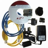
Kit Contents
CP2201 Evaluation Board, Power Adapter, CAT5e Ethernet Cable, CD-ROM, Quick-Start Guide
For Use With/related Products
CP2201
Lead Free Status / RoHS Status
Contains lead / RoHS non-compliant
Lead Free Status / RoHS Status
Lead free / RoHS Compliant, Contains lead / RoHS non-compliant
Other names
336-1316
Available stocks
Company
Part Number
Manufacturer
Quantity
Price
Company:

Part Number:
CP2201EK
Manufacturer:
SiliconL
Quantity:
8


CP2200/1
15.3. Loopback Mode
Loopback Mode provides the ability to transfer data from the physical layer’s output directly to it’s input to aid in
system debugging. When PHYCN.3 is set to ‘1’, transmit data is looped back to the receiver via an internal analog
path. The transmit drivers and receive input circuitry are bypassed, isolating the device from the network. This
prevents network traffic from affecting the result of any system self-tests and guarantees a collision-free
environment.
15.4. Link Integrity Function
The Link Integrity function provides the ability to detect and respond to a 10 BASE-T link failure. When such a
failure is detected, the transmitter and receiver are automatically disabled, and the state of the link is reported in
LINKSTA (PHYCN.0). The host can disable the link integrity function by clearing LINKINT (PHYCF.6) to ‘0’. When
the link integrity function is disabled, the physical layer will operate regardless of the presence of link pulses.
15.5. Receiver Smart Squelch and Automatic Polarity Correction
The physical layer receiver can detect and correct for noise or incorrect polarity of the received signal. If the
receiver Smart Squelch feature is enabled by setting SMSQ (PHYCF.7) to ‘1’, the receiver circuitry performs a
combination of amplitude and timing measurements (in accordance with IEEE 802.3) to determine the validity of
received data. This prevents noise from falsely triggering the receiver in the absence of valid data.
Automatic polarity correction can automatically detect and correct the polarity of the received data to compensate
for a wiring error at either end of the 10 BASE-T cable. When automatic polarity correction is enabled by setting
AUTOPOL (PHYCF.1) to ‘1’, the polarity of the receive data is indicated in POLREV (PHYCN.1). When automatic
polarity detection is disabled, the polarity of the receive data can be manually reversed by setting REVPOL
(PHYCF.0) to ‘1’.
15.6. Transmitter Jabber Function
Provides the ability to automatically disable the transmitter if software attempts to transmit a packet longer than the
maximum allowed packet length (per IEEE 802.3). The host processor will be notified via the Jabber Detected
Interrupt if a jabber condition is automatically handled by the hardware. Enabling the jabber function is
recommended to ensure that the embedded system using the CP2200/1 for Ethernet communication does not
generate a jabber condition on the wire.
Rev. 1.0
89
Related parts for CP2201EK
Image
Part Number
Description
Manufacturer
Datasheet
Request
R

Part Number:
Description:
IC ETH CTRLR SNGL-CHIP 28QFN
Manufacturer:
Silicon Laboratories Inc
Datasheet:

Part Number:
Description:
Ethernet ICs Ethernet Controller
Manufacturer:
Silicon Laboratories Inc

Part Number:
Description:
SMD/C°/SINGLE-ENDED OUTPUT SILICON OSCILLATOR
Manufacturer:
Silicon Laboratories Inc
Part Number:
Description:
Manufacturer:
Silicon Laboratories Inc
Datasheet:
Part Number:
Description:
N/A N/A/SI4010 AES KEYFOB DEMO WITH LCD RX
Manufacturer:
Silicon Laboratories Inc
Datasheet:
Part Number:
Description:
N/A N/A/SI4010 SIMPLIFIED KEY FOB DEMO WITH LED RX
Manufacturer:
Silicon Laboratories Inc
Datasheet:
Part Number:
Description:
N/A/-40 TO 85 OC/EZLINK MODULE; F930/4432 HIGH BAND (REV E/B1)
Manufacturer:
Silicon Laboratories Inc
Part Number:
Description:
EZLink Module; F930/4432 Low Band (rev e/B1)
Manufacturer:
Silicon Laboratories Inc
Part Number:
Description:
I°/4460 10 DBM RADIO TEST CARD 434 MHZ
Manufacturer:
Silicon Laboratories Inc
Part Number:
Description:
I°/4461 14 DBM RADIO TEST CARD 868 MHZ
Manufacturer:
Silicon Laboratories Inc
Part Number:
Description:
I°/4463 20 DBM RFSWITCH RADIO TEST CARD 460 MHZ
Manufacturer:
Silicon Laboratories Inc
Part Number:
Description:
I°/4463 20 DBM RADIO TEST CARD 868 MHZ
Manufacturer:
Silicon Laboratories Inc
Part Number:
Description:
I°/4463 27 DBM RADIO TEST CARD 868 MHZ
Manufacturer:
Silicon Laboratories Inc
Part Number:
Description:
I°/4463 SKYWORKS 30 DBM RADIO TEST CARD 915 MHZ
Manufacturer:
Silicon Laboratories Inc