EVALVIPER17L-7W STMicroelectronics, EVALVIPER17L-7W Datasheet - Page 20
EVALVIPER17L-7W
Manufacturer Part Number
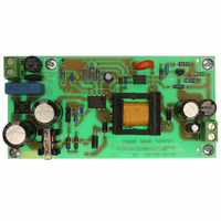
EVALVIPER17L-7W
Description
BOARD EVAL FOR VIPER17L
Manufacturer
STMicroelectronics
Series
VIPer™ plusr
Type
MOSFET & Power Driverr
Specifications of EVALVIPER17L-7W
Main Purpose
AC/DC, Primary Side
Outputs And Type
1, Isolated
Power - Output
7W
Voltage - Output
12V
Current - Output
600mA
Voltage - Input
85 ~ 265VAC
Regulator Topology
Flyback
Frequency - Switching
60kHz
Board Type
Fully Populated
Utilized Ic / Part
VIPer17
Input Voltage
90 V to 265 V
Output Voltage
12 V
Product
Power Management Modules
Silicon Manufacturer
ST Micro
Silicon Core Number
VIPer17
Kit Application Type
Power Management - Voltage Regulator
Application Sub Type
Off Line Power Converter
Kit Contents
Board
Lead Free Status / RoHS Status
Lead free / RoHS Compliant
For Use With/related Products
VIPer17
Other names
497-6447


Operation descriptions
7.9
7.10
20/31
About CONT pin
Referring to the
1.
2.
The
activate one or plus of the CONT pin functions.
Figure 27. CONT pin configuration
Table 9.
1. R
Feed-back and overload protection (OLP)
The VIPER17 is a current mode converter: the feedback pin controls the PWM operation,
controls the burst mode and actives the overload protection.
Figure 29
With the feedback pin voltage between
current is sensed and converted in voltage that is applied to the non inverting pin of the
PWM comparator. See
This voltage is compared with the one on the feedback pin through a voltage divider on
cycle by cycle basis. When these two voltages are equal, the PWM logic orders the switch
off of the power MOSFET. The drain current is always limited to I
In case of overload the feedback pin increases in reaction to this event and when it goes
higher than
the OCP comparator,
Table 9 on page 20
LIM
Current Limit set point
Over voltage protection on the converter output voltage
Auxiliary
winding
Daux
has to be fixed before of R
Function / component
I
show the internal current mode structure.
Dlim
V
CONT pin configurations
I
FBlin
Dlim
reduction + OVP
R OV P
Figure
, the PWM comparator is disabled and the drain current is limited to I
reduction
OVP
seeFigure 2 on page
27, through the CONT pin, the below features can be implemented:
Figure 2 on page
referring to the
CONT
R LIM
OVP
Doc ID 14419 Rev 7
V
Figure
FBbm
3.
LOGIC
See
See
OVP
3.
OVP
≥ 80 KΩ
START
R
SOFT
and
Figure 16
Figure 16
LIM
27, lists the external components needed to
(1)
V
FBlin
, see
BLOCK
OCP
Figure 28 on page 22
Table 8 on page
See
See
From R SENSE
Dlim
Equation 4
Equation 4
R
No
OVP
value.
+
-
OCP
7, the drain
to GATE driver
VIPER17
and
D
Yes
Yes
Dlim
No
AUX
by
Related parts for EVALVIPER17L-7W
Image
Part Number
Description
Manufacturer
Datasheet
Request
R

Part Number:
Description:
STMicroelectronics [RIPPLE-CARRY BINARY COUNTER/DIVIDERS]
Manufacturer:
STMicroelectronics
Datasheet:
Part Number:
Description:
STMicroelectronics [LIQUID-CRYSTAL DISPLAY DRIVERS]
Manufacturer:
STMicroelectronics
Datasheet:

Part Number:
Description:
BOARD EVAL FOR MEMS SENSORS
Manufacturer:
STMicroelectronics
Datasheet:
Part Number:
Description:
NPN TRANSISTOR POWER MODULE
Manufacturer:
STMicroelectronics
Datasheet:
Part Number:
Description:
TURBOSWITCH ULTRA-FAST HIGH VOLTAGE DIODE
Manufacturer:
STMicroelectronics
Datasheet:
Part Number:
Description:
Manufacturer:
STMicroelectronics
Datasheet:
Part Number:
Description:
DIODE / SCR MODULE
Manufacturer:
STMicroelectronics
Datasheet:
Part Number:
Description:
DIODE / SCR MODULE
Manufacturer:
STMicroelectronics
Datasheet:
Part Number:
Description:
Search -----> STE16N100
Manufacturer:
STMicroelectronics
Datasheet:
Part Number:
Description:
Search ---> STE53NA50
Manufacturer:
STMicroelectronics
Datasheet:
Part Number:
Description:
NPN Transistor Power Module
Manufacturer:
STMicroelectronics
Datasheet:
Part Number:
Description:
DIODE / SCR MODULE
Manufacturer:
STMicroelectronics
Datasheet: