EVALVIPER17L-7W STMicroelectronics, EVALVIPER17L-7W Datasheet - Page 23
EVALVIPER17L-7W
Manufacturer Part Number
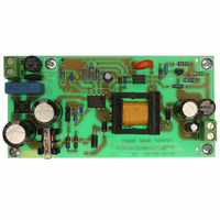
EVALVIPER17L-7W
Description
BOARD EVAL FOR VIPER17L
Manufacturer
STMicroelectronics
Series
VIPer™ plusr
Type
MOSFET & Power Driverr
Specifications of EVALVIPER17L-7W
Main Purpose
AC/DC, Primary Side
Outputs And Type
1, Isolated
Power - Output
7W
Voltage - Output
12V
Current - Output
600mA
Voltage - Input
85 ~ 265VAC
Regulator Topology
Flyback
Frequency - Switching
60kHz
Board Type
Fully Populated
Utilized Ic / Part
VIPer17
Input Voltage
90 V to 265 V
Output Voltage
12 V
Product
Power Management Modules
Silicon Manufacturer
ST Micro
Silicon Core Number
VIPer17
Kit Application Type
Power Management - Voltage Regulator
Application Sub Type
Off Line Power Converter
Kit Contents
Board
Lead Free Status / RoHS Status
Lead free / RoHS Compliant
For Use With/related Products
VIPer17
Other names
497-6447


VIPER17
7.11
7.12
Burst-mode operation at no load or very light load
When the load decrease the feedback loop reacts lowering the feedback pin voltage. If it
falls down the burst mode threshold, V
switched on. After the MOSFET stops, as a result of the feedback reaction to the energy
delivery stop, the feedback pin voltage increases and exceeding the level, V
V
reported on
where power MOSFET is switching to period of time where power MOSFET is not switching;
this device working mode is the burst mode. The power delivered to output during switching
periods exceeds the load power demands; the excess of power is balanced from not
switching period where no power is processed. The advantage of burst mode operation is
an average switching frequency much lower then the normal operation working frequency,
up to some hundred of hertz, minimizing all frequency related losses. During the burst-mode
the drain current peak is clamped to the level, I
Figure 30. Burst mode timing diagram, light load management
Brown-out protection
Brown-out protection is a not-latched shutdown function activated when a condition of mains
under voltage is detected. The Brown-out comparator is internally referenced to V
threshold, see
is below this internal reference. Under this condition the power MOSFET is turned off. Until
the Brown out condition is present, the V
V
voltage hysteresis is present to improve the noise immunity.
The switching operation is restarted as the voltage on the pin is above the reference plus the
before said voltage hysteresis. See
The Brown-out comparator is provided also with a current hysteresis, I
has to set the rectified input voltage above which the power MOSFET starts switching after
brown out event, V
switched off, V
be set separately.
FBbmhys
DDon
I DRAIN
V
FBbm
V FB
and the UVLO thresholds, as shown in the timing diagram of
, the power MOSFET starts switching again. The burst mode thresholds are
Table 8
Normal - mode
Normal - mode
Normal - mode
INoff
Table 8 on page 7
. Thanks to the I
INon
and
, and the rectified input voltage below which the power MOSFET is
Figure 30
Doc ID 14419 Rev 7
, and disables the PWM if the voltage applied at the BR pin
BRhyst
shows this behavior. Systems alternates period of time
Figure 5 on page 9
FBbm
, see
DD
, the power MOSFET is not more allowed to be
voltage continuously oscillates between the
Burst-mode
Burst-mode
Burst-mode
Table 8 on page 7
D_BM
, reported on
.
, these two thresholds can
Table 8
Operation descriptions
Figure 31 on page 24
BRhyst
.
Normal - mode
Normal - mode
Normal - mode
FBbm
. The designer
100
hyster.
hyster.
50 mV
50 mV
+
BRth
23/31
t
t
t
t
. A
Related parts for EVALVIPER17L-7W
Image
Part Number
Description
Manufacturer
Datasheet
Request
R

Part Number:
Description:
STMicroelectronics [RIPPLE-CARRY BINARY COUNTER/DIVIDERS]
Manufacturer:
STMicroelectronics
Datasheet:
Part Number:
Description:
STMicroelectronics [LIQUID-CRYSTAL DISPLAY DRIVERS]
Manufacturer:
STMicroelectronics
Datasheet:

Part Number:
Description:
BOARD EVAL FOR MEMS SENSORS
Manufacturer:
STMicroelectronics
Datasheet:
Part Number:
Description:
NPN TRANSISTOR POWER MODULE
Manufacturer:
STMicroelectronics
Datasheet:
Part Number:
Description:
TURBOSWITCH ULTRA-FAST HIGH VOLTAGE DIODE
Manufacturer:
STMicroelectronics
Datasheet:
Part Number:
Description:
Manufacturer:
STMicroelectronics
Datasheet:
Part Number:
Description:
DIODE / SCR MODULE
Manufacturer:
STMicroelectronics
Datasheet:
Part Number:
Description:
DIODE / SCR MODULE
Manufacturer:
STMicroelectronics
Datasheet:
Part Number:
Description:
Search -----> STE16N100
Manufacturer:
STMicroelectronics
Datasheet:
Part Number:
Description:
Search ---> STE53NA50
Manufacturer:
STMicroelectronics
Datasheet:
Part Number:
Description:
NPN Transistor Power Module
Manufacturer:
STMicroelectronics
Datasheet:
Part Number:
Description:
DIODE / SCR MODULE
Manufacturer:
STMicroelectronics
Datasheet: