EVALVIPER17L-7W STMicroelectronics, EVALVIPER17L-7W Datasheet - Page 24
EVALVIPER17L-7W
Manufacturer Part Number
EVALVIPER17L-7W
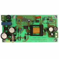
Description
BOARD EVAL FOR VIPER17L
Manufacturer
STMicroelectronics
Series
VIPer™ plusr
Type
MOSFET & Power Driverr
Specifications of EVALVIPER17L-7W
Main Purpose
AC/DC, Primary Side
Outputs And Type
1, Isolated
Power - Output
7W
Voltage - Output
12V
Current - Output
600mA
Voltage - Input
85 ~ 265VAC
Regulator Topology
Flyback
Frequency - Switching
60kHz
Board Type
Fully Populated
Utilized Ic / Part
VIPer17
Input Voltage
90 V to 265 V
Output Voltage
12 V
Product
Power Management Modules
Silicon Manufacturer
ST Micro
Silicon Core Number
VIPer17
Kit Application Type
Power Management - Voltage Regulator
Application Sub Type
Off Line Power Converter
Kit Contents
Board
Lead Free Status / RoHS Status
Lead free / RoHS Compliant
For Use With/related Products
VIPer17
Other names
497-6447


Operation descriptions
24/31
Figure 31. Brown-out protection: BR external setting and timing diagram
Rh
Rl
V IN
BR
Fixed the V
can be established for the calculation of the resistors R
Equation 9
Equation 10
For a proper operation of this function, V
minimum mains and V
minimum mains and maximum load.
The BR pin is a high impedance input connected to high value resistors, thus it is prone to
pick up noise, which might alter the OFF threshold when the converter operates or gives
origin to undesired switch-off of the device during ESD tests.
It is possible to bypass the pin to ground with a small film capacitor (e.g. 1-10 nF) to prevent
any malfunctioning of this kind.
If the brown-out function is not used the BR pin has to be connected to GND, ensuring that
the voltage is lower than the minimum of V
enable the brown-out function the BR pin voltage has to be higher than the maximum of
V
DIS
I BRhyst
threshold (150 mV, see
INon
V BRth
V DIS
and the V
Vcc
+
-
+
-
R
V
DD
L
R
IN off
=
H
=
−
INoff
AC_OK Disable
V
I
V
less than the minimum voltage on the input bulk capacitor at
BRhyst
BRhyst
INon
Table 8
levels, with reference to
Doc ID 14419 Rev 7
V in_OK
−
V
+
I
).
BRhyst
INoff
V
INon
IN on
−
V
DIS
V
−
INoff
BRhyst
V DRAIN
V INon
V INoff
V
must be less than the peak voltage at
V in_OK
I BRhyst
V DDon
V DDoff
V OUT
threshold (50 mV, see
V BRth
INoff
V
V BR
V IN
I
BR
−
DD
V
×
−
BRth
R
V
Figure 31
BRhyst
L
H
+
and R
R
V
I
BRhyst
BRhyst
L
×
L
I
V
BRhyst
, the following relationships
:
BRth
Table 8
). In order to
VIPER17
t
t
t
t
t
t
t
t
t
t
t
t
t
t
Related parts for EVALVIPER17L-7W
Image
Part Number
Description
Manufacturer
Datasheet
Request
R

Part Number:
Description:
STMicroelectronics [RIPPLE-CARRY BINARY COUNTER/DIVIDERS]
Manufacturer:
STMicroelectronics
Datasheet:
Part Number:
Description:
STMicroelectronics [LIQUID-CRYSTAL DISPLAY DRIVERS]
Manufacturer:
STMicroelectronics
Datasheet:

Part Number:
Description:
BOARD EVAL FOR MEMS SENSORS
Manufacturer:
STMicroelectronics
Datasheet:
Part Number:
Description:
NPN TRANSISTOR POWER MODULE
Manufacturer:
STMicroelectronics
Datasheet:
Part Number:
Description:
TURBOSWITCH ULTRA-FAST HIGH VOLTAGE DIODE
Manufacturer:
STMicroelectronics
Datasheet:
Part Number:
Description:
Manufacturer:
STMicroelectronics
Datasheet:
Part Number:
Description:
DIODE / SCR MODULE
Manufacturer:
STMicroelectronics
Datasheet:
Part Number:
Description:
DIODE / SCR MODULE
Manufacturer:
STMicroelectronics
Datasheet:
Part Number:
Description:
Search -----> STE16N100
Manufacturer:
STMicroelectronics
Datasheet:
Part Number:
Description:
Search ---> STE53NA50
Manufacturer:
STMicroelectronics
Datasheet:
Part Number:
Description:
NPN Transistor Power Module
Manufacturer:
STMicroelectronics
Datasheet:
Part Number:
Description:
DIODE / SCR MODULE
Manufacturer:
STMicroelectronics
Datasheet: