EVL250W-ATX80PL STMicroelectronics, EVL250W-ATX80PL Datasheet
EVL250W-ATX80PL
Specifications of EVL250W-ATX80PL


Related parts for EVL250W-ATX80PL


EVL250W-ATX80PL Summary of contents
Page 1
... EVL250W-ATX80PL: 80 PLUS Introduction This application note describes the characteristics and performance of a 250 W wide range input and power factor corrected power supply designed to be used in an ATX application. Good electrical performance allows the meeting of the 80 PLUS The converter consists of four main blocks: ■ ...
Page 2
Contents Contents 1 Main characteristics and circuit description . . . . . . . . . . . . . . . . . . . . . 5 2 Asymmetrical half bridge operation . . . . . ...
Page 3
... Climate Savers Computing Initiative . . . . . . . . . . . . . . . . . . . . . . . . . . . . . . . . . . . . . . . . . . 20 Table 5. No-load consumption . . . . . . . . . . . . . . . . . . . . . . . . . . . . . . . . . . . . . . . . . . . . . . . . . . . . . 20 Table 6. Low load efficiency @ 115 Vrms . . . . . . . . . . . . . . . . . . . . . . . . . . . . . . . . . . . . . . . . . . . . 21 Table 7. Low load efficiency @ 230 Vrms . . . . . . . . . . . . . . . . . . . . . . . . . . . . . . . . . . . . . . . . . . . . 22 Table 8. PF vs. load . . . . . . . . . . . . . . . . . . . . . . . . . . . . . . . . . . . . . . . . . . . . . . . . . . . . . . . . . . . . . 25 Table 9. EVL250W-ATX80PL bill of materials . . . . . . . . . . . . . . . . . . . . . . . . . . . . . . . . . . . . . . . . . 28 Table 10. Winding characteristics . . . . . . . . . . . . . . . . . . . . . . . . . . . . . . . . . . . . . . . . . . . . . . . . . . . . 36 Table 11. Winding characteristics . . . . . . . . . . . . . . . . . . . . . . . . . . . . . . . . . . . . . . . . . . . . . . . . . . . . 38 Table 12. Winding characteristics . . . . . . . . . . . . . . . . . . . . . . . . . . . . . . . . . . . . . . . . . . . . . . . . . . . . 41 Table 13. Document revision history . . . . . . . . . . . . . . . . . . . . . . . . . . . . . . . . . . . . . . . . . . . . . . . . . 44 Doc ID 17402 Rev 1 ...
Page 4
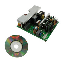
List of figures List of figures Figure 1. 250 W ATX SMPS demonstration board . . . . . . . . . . . . . . . . . . . . . . . . . . ...
Page 5
... Safety: according to EN60950 ● EMI: according to EN55022 - class B The EVL250W-ATX80PL demonstration board is made up of four main blocks, the schematics are shown in The front-end PFC stage is realized using a boost topology working in line modulated fixed off time (LM-FOT) mode, described in STMicroelectronics’ application notes, AN1792; ...
Page 6
Main characteristics and circuit description and protection needed by the AHB stage and an interface for the PFC controller. The L6591 includes two gate drivers for the half bridge MOSFETs and a fixed frequency complementary PWM logic with 50 % ...
Page 7
AN3203 The PFC_STOP pin is the interface for the PFC controller connected to the L6563S RUN pin through R104 and it stops the PFC operation (not latched) in case of overload, output short-circuit or transformer saturation detection. The ...
Page 8
Main characteristics and circuit description Figure 2. Electrical diagram: Input EMI filter and PFC stage 8/45 Doc ID 17402 Rev 1 AN3203 AM02518v1 ...
Page 9
AN3203 Figure 3. Electrical diagram: AHB stage Main characteristics and circuit description Doc ID 17402 Rev 1 AM02519v1 9/45 ...
Page 10
Main characteristics and circuit description Figure 4. Electrical diagram: DC-DC stage 10/45 Doc ID 17402 Rev 1 AN3203 AM02520v1 ...
Page 11
AN3203 Figure 5. Electrical diagram: Standby stage Main characteristics and circuit description Doc ID 17402 Rev 1 AM02521v1 11/45 ...
Page 12
Asymmetrical half bridge operation 2 Asymmetrical half bridge operation 2.1 AHB typical waveforms In Figure 6 the primary side key waveforms during steady-state operation with full load applied are shown. cycle. The AHB stage has been designed to operate at ...
Page 13
AN3203 The signal HVG is the sum of the half bridge node (FGND pin of L6591) and the high side gate driver voltages. This peculiarity allows both waveforms and the ZVS operation for the high side MOSFET to be checked. ...
Page 14
Asymmetrical half bridge operation Figure 8. AHB transitions detail @ 20 % rated load Ch1: LVG pin voltage (yellow) Ch3: HVG pin voltage (purple) Ch4: Primary winding current (green) The key waveforms at the secondary side are shown in while ...
Page 15
AN3203 Figure 9. AHB secondary side key waveforms @ full load Ch2: Q201 and Q202 drain pin (blue) Ch3: FGND pin voltage (purple) Ch4: Diode D13 current (green) In order to improve the overall efficiency of the power supply, synchronous ...
Page 16
Asymmetrical half bridge operation 2.2 Short-circuit protection In case of a short-circuit at the AHB output the overload protection (OLP) is activated. Figure 10 shows the pins involved in this function. When the short-circuit is applied, the COMP pin saturates ...
Page 17
AN3203 3 Complete system 3.1 Overvoltage protection Every output is protected against overvoltage. The + and +3.3 V are monitored on the auxiliary power supply schematic page. They use three Zener diodes to fix the three overvoltage ...
Page 18
Complete system Figure 12. Load transient output Figure 13. Load transient on +3.3 V output 3.3 Standby operation When the PS_ON is not high, the system is in standby mode. Good performance is obtained thanks to the ...
Page 19
AN3203 4 Electrical performance 4.1 Efficiency measurement and no-load consumption The efficiency measurements taken at the two nominal voltages are seen in the following tables. The +5 V_SB output was unloaded during these measurements. Table 1. Efficiency @ 115 Vrms ...
Page 20
Electrical performance This demonstration board is compliant with the 80 PLUS please refer to Table Similar levels of efficiency and power factor are defined also by the Climate Savers Computing Initiative. According to the measurements carried out, the demonstration board ...
Page 21
AN3203 Figure 15. No-load consumption Some measurements with low output loads were also taken. They refer only to the operation of the auxiliary stage, while the other stages are off. Results are shown in Table 7 and plotted in 13221 ...
Page 22
Electrical performance Table 7. Low load efficiency @ 230 Vrms Vout [V] 4.994 4.994 4.994 4.994 4.994 4.994 4.994 4.994 4.994 4.994 Figure 16. Efficiency at low loads 85.0% 80.0% 75.0% 70.0% 65.0% 60.0% 55.0% 50.0% 22/45 Iout [mA] Pout ...
Page 23
AN3203 4.2 Thermal considerations This demonstration board has been designed for operation with forced air cooling, very common in ATX power supply applications. As the component temperatures depend on the type of fan used and on the airflow path inside ...
Page 24
Electrical performance 4.3 Harmonic content measurement The front-end PFC stage provides the reduction of the mains harmonic, allowing European EN61000-3-2 and Japanese JEITA–MITI standards for class D equipment to be met. Figure 18 shows the harmonic contents of the mains ...
Page 25
AN3203 Figure 20. PF vs. input voltage 1.000 0.975 0.950 0.925 0.900 PF 0.875 0.850 0.825 0.800 Figure 21. THD vs. input voltage 20.00 18.00 16.00 14.00 12.00 10.00 THD [%] 8.00 6.00 4.00 2.00 0.00 Table 8. PF vs. ...
Page 26
Conducted noise measurements (pre-compliance test) 5 Conducted noise measurements (pre-compliance test) Figure 22, 23, 24, and detection taken at both nominal voltages. All the measurements are performed with full load output and only consider the worst phase. The average measurements ...
Page 27
AN3203 Figure 24. CE average measurement@115 Vac and full load Figure 25. CE average measurement@230 Vac and full load Conducted noise measurements (pre-compliance test) Doc ID 17402 Rev 1 27/45 ...
Page 28
... Parts list 6 Parts list Table 9. EVL250W-ATX80PL bill of materials Ref Value C1 220 µF C2 100 nF C3 1.0 µ µ µF C6 0.1 µ 560 pF C10 330 pF C11 470 pF C12 220 nF C13 1 nF C14 33 nF C15 10 nF C101 1.0 µF C102 0.1 µF C103 22 µ ...
Page 29
... AN3203 Table 9. EVL250W-ATX80PL bill of materials (continued) Ref Value C207 470 µF C208 0.1 µF C209 2.2 µF C210 2.2 µF C301 1500 µF C302 1500 µF C303 1500 µF C304 1.2 nF C305 0.1 µF C306 4.7 µF C307 0.1 µF C308 ...
Page 30
... Parts list Table 9. EVL250W-ATX80PL bill of materials (continued) Ref Value C607 0.1 µF C608 10 nF C609 0.1 µF C611 220 nF C612 47 nF C613 10 nF C614 0.1 µF C615 10 nF CN1 AC INLET CX1 470 nF CX3 680 nF CY1 2N2 CY2 2N2 CY3 4N7 D1 D15XB60 ...
Page 31
... AN3203 Table 9. EVL250W-ATX80PL bill of materials (continued) Ref Value D609 LL4148 F1 FUSE - 10A IC1 L6563S IC2 L6591 IC3 VIPER27HN IC200 TL431AIZ IC300 L6727 IC500 L6727 IC600 TS431AIZ L1 2x4 mH L2 2xJUMPER L3 60 µH L4 870 µH L5 0.75 µH L201 3.7 µH L301 3.7 µH L501 3.7 µ ...
Page 32
... Parts list Table 9. EVL250W-ATX80PL bill of materials (continued) Ref Value Q601 MMBT3904 Q603 MMBT3904 Q604 MMBT3904 Q605 MMBT3906 R1 0R33 R2 0R33 2.2 Meg R9 2.2 Meg R10 2.2 Meg R11 51 K R12 1 Meg R13 2.4 K R14 6.8 K R15 2.4 K R16 220 K R17 1.5 Meg R18 1 ...
Page 33
... AN3203 Table 9. EVL250W-ATX80PL bill of materials (continued) Ref Value R101 0.18 R R103 10 R R104 4.7 K R105 100 K R107 20 K R108 36 K R109 20 R R110 47 K R111 20 R R112 47 K R113 1 K R114 2.2 R R115 2.2 R R116 100 K R201 2.2 R R202 15 K R203 ...
Page 34
... Parts list Table 9. EVL250W-ATX80PL bill of materials (continued) Ref Value R308 10 R R309 7.5 K R310 6.34 K R311 10 K R312 2 K R313 0 R R314 0 R R501 22 R R502 22 R R503 22 R R504 22 R R505 47 K R506 47 K R507 10 R R508 10 R R509 7.5 K ...
Page 35
... AN3203 Table 9. EVL250W-ATX80PL bill of materials (continued) Ref Value R617 1 K R618 1.5 K R619 10 K R620 470 R R621 1 K R622 470 R R623 100 R R624 0 R R626 1 K R627 1.5 K R628 200 R RX1 680 K RX2 680 K T1 Transformer T2 Transformer VDR1 Varistor ZD601 BZV55-B18 ...
Page 36
PFC coil specification 7 PFC coil specification ● Application type: Consumer, IT ● Transformer type: Toroidal ● Coil former: none ● Max. temp. rise: 45 °C ● Max. operating ambient temp.: 60 °C 7.1 Electrical characteristics ● Converter topology: Boost, ...
Page 37
AN3203 8 AHB transformer specification ● Application type: Consumer, IT ● Transformer type: Open ● Coil former: vertical type, 6+6 pins ● Max. temp. rise: 45 °C ● Max. operating ambient temp.: 60 °C ● Mains insulation: Compliance with EN60950 ...
Page 38
AHB transformer specification Table 11. Winding characteristics Pins 4 – 3 9,10 – 7,8 7,8 – 11,12 TonFW – 9,10 11,12 – ToffFW Note: Cover wire ends with silicon/teflon tube: Use red tube for Ton-DR-Flyingwire Use white tube for Toff-DR-Flyingwire ...
Page 39
AN3203 Figure 30. Bottom view AHB transformer specification Doc ID 17402 Rev 1 39/45 ...
Page 40
AUX flyback transformer specification 9 AUX flyback transformer specification ● Application type: Consumer, IT ● Transformer type: Open ● Coil former: vertical type, 5+5 pins ● Max. temp. rise: 45 °C ● Max. operating ambient temp.: 60 °C ● Mains ...
Page 41
AN3203 Table 12. Winding characteristics Pins 4 – A 7,8 – 9,10 1 – – – 5 Note: Primaries A & B are in series Cover wire ends with teflon tube Figure 32. Windings position Winding ...
Page 42
AUX flyback transformer specification 9.2 Mechanical aspect and pin numbering ● Maximum height from PCB ● Coil former type: vertical, 5+5 pins (pin 6 removed) ● Pin distance: 3.81 mm ● Row distance: 10.16 mm ● Manufacturer: Magnetica ...
Page 43
AN3203 10 PCB layout Figure 34. Top side silk screen and copper Figure 35. Bottom side silk screen and copper (mirror view) Doc ID 17402 Rev 1 PCB layout 43/45 ...
Page 44
Revision history 11 Revision history Table 13. Document revision history Date 24-Aug-2010 44/45 Revision 1 Initial release Doc ID 17402 Rev 1 AN3203 Changes ...
Page 45
... AN3203 Information in this document is provided solely in connection with ST products. STMicroelectronics NV and its subsidiaries (“ST”) reserve the right to make changes, corrections, modifications or improvements, to this document, and the products and services described herein at any time, without notice. All ST products are sold pursuant to ST’s terms and conditions of sale. ...