EVL250W-ATX80PL STMicroelectronics, EVL250W-ATX80PL Datasheet - Page 7
EVL250W-ATX80PL
Manufacturer Part Number
EVL250W-ATX80PL
Description
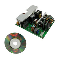
BOARD DEMO SMPS L6591/L6563S
Manufacturer
STMicroelectronics
Series
VIPer™ plusr
Datasheet
1.EVL250W-ATX80PL.pdf
(45 pages)
Specifications of EVL250W-ATX80PL
Main Purpose
Power Supply, ATX
Outputs And Type
3, Isolated
Power - Output
250W
Voltage - Output
12V, 5V, 3.3V
Current - Output
13.5A, 12A, 8A
Voltage - Input
88 ~ 264VAC
Regulator Topology
Flyback
Frequency - Switching
80kHz
Board Type
Fully Populated
Utilized Ic / Part
L6563S, L6591, L6727, VIPer27H
Input Voltage
88 VAC to 264 VAC
Output Voltage
3.3 V, 5 V, 12 V
Maximum Operating Temperature
+ 60 C
Operating Supply Voltage
80 VAC to 264 VAC
Output Power
250 W
Product
Power Management Development Tools
Lead Free Status / RoHS Status
Lead free / RoHS Compliant
For Use With/related Products
L6563S PFC controller
Other names
497-10596


AN3203
Main characteristics and circuit description
The PFC_STOP pin is the interface for the PFC controller, it is connected to the L6563S
RUN pin through R104 and it stops the PFC operation (not latched) in case of overload,
output short-circuit or transformer saturation detection.
The +5 V and +3.3 V are obtained from the +12 VA bus (AHB output) thanks to two DC-DC
converters mounted on two daughter boards. These stages are driven by the L6727, single
phase PWM controller. The topology is a standard step down. For more information please
refer to the L6727; Single phase PWM controller datasheet.
The last stage is the auxiliary power supply that provides the +5 V_SB output (2A capability)
and the VCC supply for the L6563S and L6591. It is realized with a standard flyback
topology operating in CCM/DCM with fixed frequency using the VIPer27H. This stage takes
the PFC output voltage as input and is always working when the mains is plugged in. The
VIPer27H has all the protection needed to safely drive the standby stage. It protects the
circuitry in case of overload, output short-circuit, or output overvoltage.
All the other stages (and therefore the outputs +12 V, +5 V and +3.3 V) can be turned on /
off using the signal PS_ON. If it is disconnected or connected to GND, the OPTO2 current is
zero, Q601 is open and the VCC of the L6563S and L6591 is zero. If PS_ON is connected to
+5 V_SB, the OPTO2 current turns Q601 on. This BJT, together with the Zener diode
ZD601, acts as a linear regulator and provides the supply to the PFC and AHB controllers.
The same optocoupler is used to turn off the PFC and AHB stages in case of an overvoltage
on one of the three main outputs. Such protection is realized with three Zener diodes (one
for each output) that set the OVP thresholds. If one of the three output voltages goes over its
threshold, the Zener diode conducts and turns on the latch realized with Q604 and Q605.
The current in OPTO2 is reduced to zero (overriding the PS_ON information) and the
L6563S and L6591 are turned off.
Only the +5 V_SB stays on and continues to keep the protection latched.
Doc ID 17402 Rev 1
7/45
Related parts for EVL250W-ATX80PL
Image
Part Number
Description
Manufacturer
Datasheet
Request
R

Part Number:
Description:
STMicroelectronics [RIPPLE-CARRY BINARY COUNTER/DIVIDERS]
Manufacturer:
STMicroelectronics
Datasheet:
Part Number:
Description:
STMicroelectronics [LIQUID-CRYSTAL DISPLAY DRIVERS]
Manufacturer:
STMicroelectronics
Datasheet:

Part Number:
Description:
BOARD EVAL FOR MEMS SENSORS
Manufacturer:
STMicroelectronics
Datasheet:
Part Number:
Description:
NPN TRANSISTOR POWER MODULE
Manufacturer:
STMicroelectronics
Datasheet:
Part Number:
Description:
TURBOSWITCH ULTRA-FAST HIGH VOLTAGE DIODE
Manufacturer:
STMicroelectronics
Datasheet:
Part Number:
Description:
Manufacturer:
STMicroelectronics
Datasheet:
Part Number:
Description:
DIODE / SCR MODULE
Manufacturer:
STMicroelectronics
Datasheet:
Part Number:
Description:
DIODE / SCR MODULE
Manufacturer:
STMicroelectronics
Datasheet:
Part Number:
Description:
Search -----> STE16N100
Manufacturer:
STMicroelectronics
Datasheet:
Part Number:
Description:
Search ---> STE53NA50
Manufacturer:
STMicroelectronics
Datasheet:
Part Number:
Description:
NPN Transistor Power Module
Manufacturer:
STMicroelectronics
Datasheet:
Part Number:
Description:
DIODE / SCR MODULE
Manufacturer:
STMicroelectronics
Datasheet: