MULTIPHSPOL-RD Silicon Laboratories Inc, MULTIPHSPOL-RD Datasheet
MULTIPHSPOL-RD
Specifications of MULTIPHSPOL-RD


Related parts for MULTIPHSPOL-RD

MULTIPHSPOL-RD Summary of contents
Page 1
Features Single-chip, Flash-based digital power controller Supports isolated and non-isolated applications Enables new system capabilities such as: - Adaptive dead-time control for higher efficiency - Nonlinear control for faster ...
Page 2
Si8250/1/2 2 Rev. 1.0 ...
Page 3
Section 1. Electrical Specifications . . . . . . . . . . . . . . . . . . . . . . ...
Page 4
Si8250/1/2 1. Electrical Specifications Table 1. Absolute Maximum Ratings* Parameter Ambient temperature under bias Storage temperature Voltage on any Port0 Pin with respect to GND Voltage on all other pins with respect to GND Voltage on V with respect to ...
Page 5
Table 3. Reference DAC Electrical Specifications T = –40 to +125 ° 2.5 V, SYSCLK = 25 MHz, PLLCLK = 200 MHz unless otherwise specified Parameter Resolution LSB size Integral nonlinearity (INL) Differential nonlinearity (DNL) Settling ...
Page 6
Si8250/1/2 Table 4. ADC0 (12-Bit ADC) Specifications T = –40 to +125 ° 2.5 V, SYSCLK = 25 MHz, PLLCLK = 200 MHz unless otherwise specified Parameter DC Accuracy Resolution Integral nonlinearity Differential nonlinearity Offset error ...
Page 7
Table 5. ADC1 Specifications TA = –40 to +125 ° 2.5 V, SYSCLK = 25 MHz, PLLCLK = 200 MHz unless otherwise specified. DD Parameter Sampling frequency Resolution LSB size Differential input voltage range Common-mode input voltage range ...
Page 8
Si8250/1/2 Table 7. Peak Current Limit Detector Electrical Specifications T = –40 to +125 ° 2.5 V, SYSCLK = 25 MHz, PLLCLK = 200 MHz unless otherwise specified Parameter IPK input to DPWM output latency Threshold ...
Page 9
Table 8. DPWM Specifications T = –40 to +125 ° 2.5 V, SYSCLK = 25 MHz, PLLCLK = 200 MHz unless otherwise specified Parameter Clock frequency Resolution Time resolution SYNC signal minimum LOW time SYNC pulse ...
Page 10
Si8250/1/2 Table 10. Comparator0 Specifications T = –40 to +125 ° 2.5 V, SYSCLK = 25 MHz, PLLCLK = 200 MHz unless otherwise specified Parameter V IN Low-speed supply current Full-speed supply current Hysteresis Low power ...
Page 11
Table 11. Reset Electrical Characteristics T = –40 to +125 ° 2.5 V, SYSCLK = 25 MHz, PLLCLK = 200 MHz unless otherwise specified Parameter RST output low voltage RST input high voltage RST input low ...
Page 12
Si8250/1/2 Table 13. Port I/O DC Electrical Characteristics T = –40 to +125 °C, SYSCLK = 25 MHz, PLLCLK = 200 MHz unless otherwise specified. A Parameters Port0 input voltage tolerance Port1 input voltage tolerance Output high voltage Output low ...
Page 13
Table 15. 25MHz Oscillator Specifications T = –40 to +125 ° 2.5 V, SYSCLK = 25 MHz, PLLCLK = 200 MHz unless otherwise specified Parameter Frequency Start-up time Power supply sensitivity Temperature coefficient Supply current Shutdown ...
Page 14
Si8250/1/2 2. Benefits of Digital Power Control Digitally-controlled power systems have the following key advantages over analog implementations: In-system programmability: Virtually all aspects of digital controller behavior can be changed in software locally or remotely and without hardware modification. This ...
Page 15
Product Description System Management Processor VDD 2% 25 Mhz OSC, SYSCLKIN and LFO RESET CONTROL HARDWARE DEBUG DEBUG PORT INTERRUPT CONTROL VSENSE VSENSE VREF REFDAC VREF IPK Control Processor System Management Processor VDD 50MIPS 8051 CPU SYSCLKIN and Memory ...
Page 16
Si8250/1/2 3.1. System Operation Figure 2 shows the Si8250/1/2 controlling a non- isolated dc/dc converter operating in digital voltage mode control. The output voltage signal connects to the V input through a resistive divider, limiting the SENSE common-mode voltage range ...
Page 17
The first filter stage is a PID filter providing one pole and two zeros. The second stage is selectable: a two-pole, low-pass filter (LPF) for the fastest possible response SINC (multiple zero) decimation filter for quieter ...
Page 18
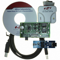
Si8250/1/2 4. Design Tools The Si8250DK development kit (Figure 3) contains everything required to develop applications with the Si825x family of digital power controllers. This kit supports all phases of power supply development from controller design through real-time system debugging. ...
Page 19
Example Applications The Si825x is the ideal choice for digitally-controlled switched mode power supplies. This section provides a quick overview of the Si825x in an isolated half-bridge dc/dc converter and a single-phase point-of-load converter. Reference designs are available for ...
Page 20
Si8250/1/2 5.2. Single-Phase Point of Load (POL) Converter 400 KHz Si8252 based single phase POL converter block diagram is shown in Figure 8. DPWM outputs PH1 and PH2 control the gates of the buck and synchronous switching ...
Page 21
Layout Considerations The mixed-signal nature of the Si8250/1/2 mandates clean bias supplies and ground returns best to provide separate ground planes for analog, digital, and power switch returns. These planes should tie together at only one point ...
Page 22
Si8250/1/2 In both cases, the bias supplies must be filtered using low ESR/ESL capacitors placed close to the IC pins. Thick copper traces should be connected to the bias pins ( and the ground pins (GND, GNDA) ...
Page 23
Pin Descriptions: Si8250/1/2 32-pin LQFP RST/C2CK 1 IPK 2 VSENSE 3 Si8250/1/2 GNDA 4 Top View VDDA 5 6 VREF 7 P1.0/VIN/AIN0 8 P1.1/AIN1 Figure 13. Example Pin Configurations Name QFN-28 LQFP-32 Pin # Pin# RST/C2CK 1 IPK 2 ...
Page 24
Si8250/1/2 Table 17. Pin Descriptions (Continued) Name QFN-28 LQFP-32 Pin # Pin# P0.5 17 P0.4 18 P0.3/XCLK 19 P0.2 20 P0.1 21 P0.0 22 PH6 23 PH5 24 PH4 25 V — DD GND — PH3 26 PH2 27 PH1 ...
Page 25
Ordering Guide Ordering Number Flash Memory Si8250-IQ Si8250-IM Si8251-IQ Si8251-IM Si8252-IQ Si8252- PWM Outputs Rev. 1.0 Si8250/1/2 UART Package ...
Page 26
Si8250/1/2 9. Package Outline: 32LQFP Figure 14 illustrates the package details for the 32-pin LQFP version of the Si8250/1/2. Table 18 lists the values for the dimensions shown in the illustration. Figure 14. 32-pin LQFP Package Diagram 26 Rev. 1.0 ...
Page 27
Table 18. LQFP-32 Package Dimensions Dimension Min A — A1 0.05 A2 1.35 b 0. 0.45 aaa bbb ccc ddd Θ 0° Notes: All dimensions shown are in millimeters (mm) unless otherwise ...
Page 28
Si8250/1/2 10. Package Outline: 28QFN Figure 15 illustrates the package details for the 28-lead QFN version of the Si8250/1/2. Table 19 lists the values for the dimensions shown in the illustration. Figure 15. 28-lead Quad Flat No-lead (QFN) Package Diagram ...
Page 29
Table 19. QFN-28 Package Dimensions Dimension Min A 0. 2.90 L 0.45 aaa bbb ddd eee Z Y Notes: 1. All dimensions shown are in millimeters (mm) unless otherwise ...
Page 30
Si8250/1 OCUMENT HANGE IST Revision 0.7 to Revision 0.8 Updated DPWM phase output drive-high and drive- low resistance in Table 8, “DPWM Specifications,” on page 9. Revision 0.8 to Revision 0.9 Updated Table 5, “ADC1 Specifications,” on ...
Page 31
N : OTES Rev. 1.0 Si8250/1/2 31 ...
Page 32
... Buyer shall indemnify and hold Silicon Laboratories harmless against all claims and damages. The sale of this product contains no licenses to Power-One’s intellectual property. Contact Power-One, Inc. for appropriate licenses. Silicon Laboratories and Silicon Labs are trademarks of Silicon Laboratories Inc. Other products or brandnames mentioned herein are trademarks or registered trademarks of their respective holders. ...