STEVAL-ISA017V1 STMicroelectronics, STEVAL-ISA017V1 Datasheet - Page 11
STEVAL-ISA017V1
Manufacturer Part Number
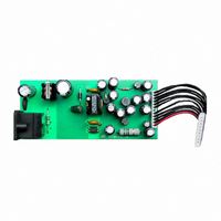
STEVAL-ISA017V1
Description
POWER SUPPLY FOR STB US-110V
Manufacturer
STMicroelectronics
Type
AC/DC Switching Convertersr
Specifications of STEVAL-ISA017V1
Mfg Application Notes
Quasi AppNote
Design Resources
STEVAL-ISA017V1 Gerber Files STEVAL-ISA017V1 Schematic STEVAL-ISA017V1 Bill of Materials
Main Purpose
AC/DC, Primary Side
Outputs And Type
6, Non-Isolated
Power - Output
17W
Voltage - Output
1.23V, 5V, 2.5V, 12V, 3.3V, 8V
Current - Output
1.7A, 1A, 700mA, 500mA, 450mA, 40mA
Voltage - Input
88 ~ 135VAC
Regulator Topology
Flyback
Board Type
Fully Populated
Utilized Ic / Part
L6565
Input Voltage
88 V to 138 V
Output Voltage
1.2 V to 12 V
Product
Power Management Modules
Lead Free Status / RoHS Status
Lead free / RoHS Compliant
Frequency - Switching
-
Lead Free Status / Rohs Status
Lead free / RoHS Compliant
For Use With/related Products
L6565
Other names
497-5680
Available stocks
Company
Part Number
Manufacturer
Quantity
Price


Error Amplifier Block (see fig. 17b):
The Error Amplifier (E/A) inverting input is used in primary feedback technique to compare a partition of the volt-
age generated by the auxiliary winding with the internal reference, to achieve converter's output voltage regu-
lation (see "Application Ideas", fig. 24). With secondary feedback (typically using a TL431 at the secondary side
and an optocoupler to transfer output voltage information to the primary side through the isolation barrier) the
E/A can be used as an inverting level-shifter to achieve negative feedback and shape the loop gain (see "Ap-
plication Ideas", fig. 23).
The E/A output is used typically for control loop compensation, realized with an RC network connected to the
inverting input. With other secondary feedback techniques, the output is driven directly by an emitter-grounded
optocoupler to modulate the duty cycle (the inverting input will be grounded in that case - see figure 23 in "Ap-
plication Ideas").
Current Comparator, PWM Latch and Hiccup-mode OCP (see fig. 17b):
The current comparator senses the voltage across the current sense resistor (Rs) and, by comparing it with the
programming signal delivered by the feedforward block, determines the exact time when the external MOSFET
is to be switched off. The PWM latch avoids spurious switching of the MOSFET, which might result from the
noise generated ("double-pulse suppression").
A comparator senses the voltage on the current sense input and disables the gate driver if the voltage at the pin
exceeds 2 V. Such anomalous condition is typically generated by a short circuit on the secondary rectifier or on
the secondary winding. To re-enable the driver, first the IC must be turned off and then can be restarted, that is
the Vcc voltage must fall below the UVLO threshold.
When the gate driver is disabled the quiescent current of the IC is unchanged and, since no energy is coming
from the self-supply circuit, the Vcc capacitor will be discharged below the UVLO threshold after some time.
Then the device will initiate a new start-up cycle. In case of failure of the secondary diode the resulting behavior
will be a low-frequency intermittent operation (Hiccup-mode operation), with very low stress on the power circuit.
Gate Driver (see fig. 18):
A totem pole buffer, with 400mA source and sink capability, drives the external MOSFET. It is made up of a
high-side NPN Darlington and a low-side MOSFET. In this way there is no need of an external diode clamp to
prevent the voltage at the gate drive output (pin 7, GD) from being pulled too negative.
An internal pull-down circuit holds the output low when the device is in UVLO conditions, to ensure that the ex-
ternal MOSFET cannot be turned on accidentally (e.g. at power-on).
Figure 18. Gate driver with UVLO pull-down
DRIVER
8
6
GND
Vcc
UVLO
L6565
7
GD
Q
L6565
11/17
Related parts for STEVAL-ISA017V1
Image
Part Number
Description
Manufacturer
Datasheet
Request
R

Part Number:
Description:
BOARD RGB CTR ST7,STP08C596MTR
Manufacturer:
STMicroelectronics
Datasheet:

Part Number:
Description:
Power Management IC Development Tools Full Speed USB to RS232 Bridge Demo
Manufacturer:
STMicroelectronics
Datasheet:
Part Number:
Description:
Power Management IC Development Tools 2.5W solar eval BRD USB SPV1040 LD39050
Manufacturer:
STMicroelectronics
Datasheet:

Part Number:
Description:
BOARD EVAL FOR MEMS SENSORS
Manufacturer:
STMicroelectronics
Datasheet:

Part Number:
Description:
KIT DEV STARTER ST10F276Z5
Manufacturer:
STMicroelectronics
Datasheet:

Part Number:
Description:
BOARD EVAL HDMI $ VIDEO SWITCH
Manufacturer:
STMicroelectronics
Datasheet:

Part Number:
Description:
BOARD DEMO ACCELEROMETER DIL24
Manufacturer:
STMicroelectronics
Datasheet:

Part Number:
Description:
BOARD STLM75/STDS75/ST72F651
Manufacturer:
STMicroelectronics
Datasheet:

Part Number:
Description:
EVAL BOARD 3AXIS MEMS ACCELLRMTR
Manufacturer:
STMicroelectronics
Datasheet:

Part Number:
Description:
BOARD EVAL 8BIT MICRO + TDE1708
Manufacturer:
STMicroelectronics
Datasheet:
Part Number:
Description:
STMicroelectronics [RIPPLE-CARRY BINARY COUNTER/DIVIDERS]
Manufacturer:
STMicroelectronics
Datasheet:
Part Number:
Description:
STMicroelectronics [LIQUID-CRYSTAL DISPLAY DRIVERS]
Manufacturer:
STMicroelectronics
Datasheet:
Part Number:
Description:
BOARD EVAL FOR MEMS SENSORS
Manufacturer:
STMicroelectronics
Datasheet: