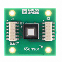
ADIS16209/PCBZ Analog Devices Inc, ADIS16209/PCBZ Datasheet

ADIS16209/PCBZ
Specifications of ADIS16209/PCBZ
Related parts for ADIS16209/PCBZ
ADIS16209/PCBZ Summary of contents
Page 1
FEATURES Dual-mode inclinometer system Dual-axis, horizontal operation, ±90° Single-axis, vertical operation, ±180° High accuracy, 0.1° Digital inclination data, 0.025° resolution Digital acceleration data, 0.244 mg resolution ±1.7 g accelerometer measurement range Digital temperature sensor output Digitally controlled bias calibration Digitally ...
Page 2
ADIS16209 TABLE OF CONTENTS Features .............................................................................................. 1 Applications ....................................................................................... 1 Functional Block Diagram .............................................................. 1 General Description ......................................................................... 1 Revision History ............................................................................... 2 Specifications ..................................................................................... 3 Timing Specifications .................................................................. 5 Timing Diagrams .......................................................................... 5 Absolute Maximum Ratings ............................................................ 6 Thermal ...
Page 3
SPECIFICATIONS T = 25°C, VDD = 3.3 V, tilt = 0°, unless otherwise noted. A Table 1. Parameter HORIZONTAL INCLINE Input Range Relative Accuracy Sensitivity VERTICAL ROTATION Input Range Relative Accuracy Sensitivity ACCELEROMETER 1 Input Range 1 Nonlinearity Alignment Error ...
Page 4
ADIS16209 Parameter LOGIC INPUTS Input High Voltage, V INH Input Low Voltage, V INL Logic 1 Input High Current, I INH Logic 0 Input Low Current, I INL All Except RST 3 RST Input Capacitance DIGITAL OUTPUTS Output ...
Page 5
TIMING SPECIFICATIONS T = 25°C, VDD = 3.3 V, tilt = 0°, unless otherwise noted. A Table 2. Parameter Description f Fast mode, SMPL_PRD ≤ 0x07 (f SCLK Normal mode, SMPL_PRD ≥ 0x08 (f t Chip select period, fast mode, ...
Page 6
ADIS16209 ABSOLUTE MAXIMUM RATINGS Table 3. Parameter Acceleration (Any Axis, Unpowered) Acceleration (Any Axis, Powered) VDD to GND Digital Input/Output Voltage to GND Analog Inputs to GND Analog Inputs to GND Operating Temperature Range Storage Temperature Range Stresses above those ...
Page 7
PIN CONFIGURATION AND FUNCTION DESCRIPTIONS NOTES CONNECT. 2. THIS IS NOT AN ACTUAL TOP VIEW, BECAUSE THE PINS ARE NOT VISIBLE FROM THE TOP. THIS IS A LAYOUT VIEW THAT REPRESENTS THE PIN CONFIGURATION IF THE ...
Page 8
ADIS16209 TYPICAL PERFORMANCE CHARACTERISTICS 0.20 0.15 0.10 0.05 0 –0.05 –0.10 –0.15 –0.20 –40 –30 –20 –10 0 INCLINATION ANGLE (Degrees) Figure 7. Horizontal Inclination Error (Eight Parts), Autonull at Horizontal Position, Stable Temperature, 3.3 V 0.3 0.2 0.1 0 ...
Page 9
V = 3.0V, 3.3V, 3.6V DD TEMP = –40°C, +25°C, +85° –0.50 –0.38 –0.26 –0.14 –0.02 0.10 0.22 SENSITIVITY ERROR (%) Figure 13. Accelerometer Output Sensitivity Error Distribution 3.0V, 3.3V, ...
Page 10
ADIS16209 THEORY OF OPERATION The ADIS16209 tilt sensing system uses gravity as its only stimulus, and a MEMS accelerometer as its sensing element. MEMS accelerometers typically employ a tiny, spring-loaded structure that is interlaced with a fixed pick-off finger structure. ...
Page 11
BASIC OPERATION The ADIS16209 requires only power/ground and SPI connec- tions. The SPI is simple to hook up and is supported by many common digital hardware platforms. Figure 20 provides a simple hook-up diagram, while Table 2, Figure 2, and ...
Page 12
ADIS16209 OUTPUT DATA REGISTERS Table 7 provides the data configuration for each output data register in the ADIS16209. Starting with the MSB of the upper byte, each output data register has the following bit sequence: new data (ND) flag, error/alarm ...
Page 13
Digital I/O Lines The ADIS16209 provides two general-purpose, digital input/output lines that have several configuration options. Table 11. Digital I/O Line Configuration Registers Function Data-Ready I/O Indicator Alarm Indicator General-Purpose I/O Configuration General-Purpose I/O Line Communication Data-Ready I/O Indicator The ...
Page 14
ADIS16209 The flash update copies the contents of all the flash backup registers into their assigned, nonvolatile flash memory loca- tions. This process takes approximately 50 ms and requires a power supply that is within the specified operating range. After ...
Page 15
Status The STATUS register provides a series of error flags that provide indicator functions for common system-level issues. All of the flags clear (set to 0) after each STATUS register read cycle error condition remains, the error flag ...
Page 16
... TOP VIEW 5.00 TYP SIDE VIEW ORDERING GUIDE Model Temperature Range ADIS16209CCCZ 1 −40°C to +125°C 1 ADIS16209/PCBZ RoHS Compliant Part. ©2008–2009 Analog Devices, Inc. All rights reserved. Trademarks and registered trademarks are the property of their respective owners. 2.6955 BSC (8× 8.373 BSC (2× ...


