DV102011 Microchip Technology, DV102011 Datasheet
DV102011
Specifications of DV102011
Available stocks


Related parts for DV102011

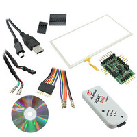
DV102011 Summary of contents
Page 1
AR1000 Series Resistive Touch Screen Controller DS41393A ...
Page 2
... PICtail, PIC logo, REAL ICE, rfLAB, Select Mode, Total 32 Endurance, TSHARC, WiperLock and ZENA are trademarks of Microchip Technology Incorporated in the U.S.A. and other countries. SQTP is a service mark of Microchip Technology Incorporated in the U.S.A. All other trademarks mentioned herein are property of their respective companies. © ...
Page 3
... Register Write - 0x21............................................................................................................. 21 7.15.6 Register Start Address Request - 0x22................................................................................. 21 7.15.7 Registers Write to EEPROM - 0x23 ...................................................................................... 21 7.15.8 EEPROM Read - 0x28 .......................................................................................................... 22 7.15.9 EEPROM Write - 0x29 .......................................................................................................... 22 7.15.10 EEPROM Write to Registers - 0x2B .................................................................................. 22 7. ALIBRATION OF OUCH ENSOR WITH © 2009 Microchip Technology, Inc. ......................................................................................................................5 ....................................................................................................................5 ....................................................................................................................6 ....................................................................................................................7 ........................................................................................................................11 C .........................................................................................23 ONTROLLER DS41393A-Page iii ...
Page 4
... Table 1: Ordering Part Numbers................................................................................................................... 2 Table 2: Pin Descriptions .............................................................................................................................. 3 Table 3 : Bill of Materials.............................................................................................................................. 4 Table 4 : 4/8-wire vs 5-wire Selection .......................................................................................................... 5 Table 5 : Communication Selection ............................................................................................................. 8 Table 6 : Communication Pins ..................................................................................................................... 8 Table 7 : Touch Coordinate Reporting Protocol......................................................................................... 11 Table 8 : Configuration Registers .............................................................................................................. 12 Table 9 : Command Set Summary............................................................................................................. 18 Table 10 : Sensor Comparison .................................................................................................................. 25 DS41393A-Page iv (†).....................................................................................................................29 FIGURES TABLES © 2009 Microchip Technology, Inc. ...
Page 5
... Built-in touch modes Communication Control AR1010 supports UART communication. AR1020 supports I2C and SPI communication. See Communication Interface section. © 2009 Microchip Technology, Inc. Touch Sensor Support: • 4 wire, 5 wire, and 8 wire analog resistive • Lead to Lead Resistance: 50Ω to 2,000Ω ...
Page 6
... SSOP, 20 pin –40ºC to +85ºC QFN, 20 pin –40ºC to +85ºC SOIC, 20 pin –40ºC to +85ºC SSOP, 20 pin Packing Tube Tube Tube T/R T/R T/R Tube Tube Tube T/R T/R T/R © 2009 Microchip Technology, Inc. ...
Page 7
... SX 5WSX VSS 20 Table 2: Pin Descriptions © 2009 Microchip Technology, Inc. Pin # QFN 18 Supply Voltage 19 Communication Selection 20 Sense Y- (8-Wire). Tie to VSS, if not used. 1 4/8-wire or 5-wire Sensor Selection 2 Touch Wake-Up 3 LED drive / SPI Interrupt. No Connect, if not used. 4 Sense Y+ (8-Wire). Tie to VSS, if not used. ...
Page 8
... ESD protection is shown in the reference design, but acceptable protection is dependent on your specific application. Ensure your ESD solution meets your design requirements. DS41393A-Page 4 Description Manufacturer 10uF, 20%, 6.3V, X7R, 0603 AVX AVX AVX NXP Yageo America Microchip © 2009 Microchip Technology, Inc. Part Number 06036D106MAT2A 0603YC104KAT2A 06035C103KAT2A PESD5V0S1BA RC0603JR-0720KL AR1010 or AR1020 ...
Page 9
... Test to ensure that selected ESD protection does not degrade touch performance. ESD protection is shown in the reference design, but acceptable protection is dependent on your specific application. Ensure your ESD solution meets your design requirements. Tie unused controller pins 5WSX-, SX+, SY-, and SY+ to VSS. © 2009 Microchip Technology, Inc. DS41393A-Page 5 ...
Page 10
... Test to ensure that selected ESD protection does not degrade touch performance. ESD protection is shown in the reference design, but acceptable protection is dependent on your specific application. Ensure your ESD solution meets your design requirements. Tie unused controller pins SX-, SY-, and SY+ to VSS. DS41393A-Page 6 © 2009 Microchip Technology, Inc. ...
Page 11
... The PESD5V0S1BA parts shown in the reference design have a typical capacitance of 35pF. Test to ensure that selected ESD protection does not degrade touch performance. ESD protection is shown in the reference design, but acceptable protection is dependent on your specific application. Ensure your ESD solution meets your design requirements. © 2009 Microchip Technology, Inc. DS41393A-Page 7 ...
Page 12
... C operates in slave mode with 7-bit address of 0x9A. The SDO pin functions as an interrupt output asserted high when data is available. Timing diagrams are shown below. 2 Figure Timing Diagram – Receive Data 2 Figure Timing Diagram – Transmit Data DS41393A-Page 8 © 2009 Microchip Technology, Inc. ...
Page 13
... The SS pin is optional for “Slave Select” functionality active (selects) when pulled low to VSS. Tie to VSS if not used. If data is clocked out when the controller has no valid data to provide, then 0x4d (ASCII "M") will be presented. Timing diagrams are shown below. Figure 11 : SPI Timing Diagram – Bit Timing © 2009 Microchip Technology, Inc. DS41393A-Page 9 ...
Page 14
... If the LED is used with SPI communication, then the LED will be off with no touch and flicker quickly (mid level On) when a touch is in progress. If the SIQ pin is not used, it must be left connect and NOT tied to circuit VDD or VSS. DS41393A-Page 10 © 2009 Microchip Technology, Inc. ...
Page 15
... The touch coordinate reporting protocol is shown below. Byte # Bit 7 Bit 6 Bit Table 7 : Touch Coordinate Reporting Protocol where Pen-Up, 1 Pen-Down R : Reserved X11-X0 : X-axis coordinate Y11-Y0 : Y-axis coordinate © 2009 Microchip Technology, Inc. Bit 4 Bit 3 Bit 2 Bit 1 Bit X11 X10 Y11 Y10 DS41393A-Page 11 ...
Page 16
... Value of: 0-40 Value of: 0-255 Value of: 0-255 Bit 3 Bit 2 Bit 1 Bit 0 Default PM0 PU2 PU1 PU0 – – 48W CCE © 2009 Microchip Technology, Inc. Value 0xC5 0x04 0x04 0x10 0x02 0x08 0x04 0x64 0x80 0xB1 0x00 0x19 0xC8 0x00 ...
Page 17
... The SpeedThreshold register sets the threshold for touch movement to be considered as slow or fast. A lower value reduces the touch movement speed that will be considered as fast. A higher value increases the touch movement speed that will be considered as fast. Valid values are as follows. 0 ≤ SpeedThrshhold ≤ 255 © 2009 Microchip Technology, Inc. DS41393A-Page 13 ...
Page 18
... A higher value will make the controller less responsive to pen ups, but will reduce the number of touch drop outs wit a lighter touch. Valid values are as follows. 0 ≤ PenUpDelay ≤ 255 Pen Up Delay Time ≈ PenUpDelay * 240μs DS41393A-Page 14 © 2009 Microchip Technology, Inc. ...
Page 19
... P=0 on touch release. TouchMode = 0b01010001 = 0x51 Report a pen up P=0 then a pen down P=1 on initial touch, followed by reporting a stream of pen downs P=1 during the touch, followed by a final pen up P=0 on touch release. TouchMode = 0b10110001 = 0xB1 © 2009 Microchip Technology, Inc. R/W R/W R/W ...
Page 20
... Calibration Mode by 12.5% to achieve full scale. 12.5% of Full Scale Location of calibration targets presented during calibration. DS41393A-Page 16 U–0 U–0 U–0 – – – 12.5% of Full Scale R/W R/W 48W CCE Bit 0 © 2009 Microchip Technology, Inc. ...
Page 21
... Microchip Technology, Inc <Header><DataSize><Command><Data>…<Data> ...
Page 22
... Receive : <0x55><0x02><Response><0x12> 7.15.2 Disable Touch - 0x13 Controller will not send any touch coordinate reports. A touch will, however, still wake up the controller if asleep. Send : <0x55><0x01><0x13> Receive : <0x55><0x02><Response><0x13> DS41393A-Page 18 © 2009 Microchip Technology, Inc. ...
Page 23
... Upper Left Upper Right Touch Sensor # Lower Left Lower Right © 2009 Microchip Technology, Inc. for initial command response st for response to 1 target touch release nd for response to 2 target touch release rd for response to 3 target touch release ...
Page 24
... Upper Right (Node 2) Lower Right (Node 0x18 0x19 0x1A 0x1B 0x1C 0x1D U–0 U–0 R/W – – XYFLIP Lower Left (Node 0x1E 0x1F 0x20 0x21 0x22 0x23 R/W R/W XFLIP YFLIP Bit 0 © 2009 Microchip Technology, Inc. Flip Y State Hi 0x24 0x25 ...
Page 25
... Receive : <0x55><0x03><Response><0x22><Register Start Address> 7.15.7 Registers Write to EEPROM - 0x23 Save Configuration Register values to EEPROM. This allows the controller to remember configurations settings through controller power cycles. Send : <0x55><0x01><0x23> Receive : <0x55><0x02><Response><0x23> © 2009 Microchip Technology, Inc. DS41393A-Page 21 ...
Page 26
... EEPROM stored Configuration Register values, without the need for issuing this command. This command eliminates the need for the power cycle. Send : <0x55><0x01><0x2B> Receive : <0x55><0x02><Response><0x2B> DS41393A-Page 22 © 2009 Microchip Technology, Inc. ...
Page 27
... Software to display the first calibration point target in the upper left quadrant of the display and prompt the user to touch and release the target. Touch and release target 8) Wait for the user to touch and release the first calibration point target. Do this by looking for a controller response of: <0x55><0x02><0x00><0x14> © 2009 Microchip Technology, Inc. DS41393A-Page 23 ...
Page 28
... Wait for the user to touch and release the fourth calibration point target. Do this by looking for a controller response of: <0x55><0x02><0x00><0x14> 15) Enable touch reporting by issuing <Enable Touch> command. Send : <0x55><0x01><0x12> Receive : <0x55><0x02><Response><0x12> DS41393A-Page 24 © 2009 Microchip Technology, Inc. ...
Page 29
... Touch inaccuracies occur from resistance changes 8 Wire More expensive than 4 wire Lower power than 5 wire More linear (without correction) than 5-wire Touch inaccuracies occur from flex layer damaged Maintains touch accuracy with resistance changes Table 10 : Sensor Comparison © 2009 Microchip Technology, Inc. Comments DS41393A-Page 25 ...
Page 30
... The measured voltage at any position across a driven axis is predictable. A touch moving in the direction of the driven axis will yield a linearly changing voltage. A touch moving perpendicular to the driven axis will yield a relatively unchanging voltage. Figure 14: 4-Wire Decoding DS41393A-Page 26 © 2009 Microchip Technology, Inc. ...
Page 31
... In a 4-wire sensor, variations in the losses manifest themselves as error or drift in the reported touch location. An 8-wire touch sensor automatically adjusts for the changes, with the additional four reference lines. The reference lines allow the controller to know what the voltage is, at the touch sensor bus bars. Figure 15: 8-Wire Decoding © 2009 Microchip Technology, Inc. DS41393A-Page 27 ...
Page 32
... The AR1000 series was designed with an understanding of the materials and processes that make up resistive touch screens. The AR1000 series touch controller is not only reliable, but can enhance the reliability and longevity of the resistive touch screen. DS41393A-Page 28 © 2009 Microchip Technology, Inc. ...
Page 33
... Exposure to maximum rating conditions for extended periods may affect device reliability. This device is sensitive to ESD damage and must be handled appropriately. Failure to properly handle and protect the device in an application may cause partial to complete failure of the device. © 2009 Microchip Technology, Inc. (†) DS41393A-Page 29 ...
Page 34
... PACKAGING 10.1 20 Lead SOIC Figure Lead SOIC Package DS41393A-Page 30 © 2009 Microchip Technology, Inc. ...
Page 35
... Lead SSOP Figure Lead SSOP Package © 2009 Microchip Technology, Inc. DS41393A-Page 31 ...
Page 36
... Lead QFN (ML) The metal plate on the package bottom can be floated, but connecting it to VSS (circuit ground) is recommended. Figure Lead QFN Package DS41393A-Page 32 © 2009 Microchip Technology, Inc. ...
Page 37
... Microchip Technology, Inc. DS41393A-Page 33 ...