ADIS16100/PCB Analog Devices Inc, ADIS16100/PCB Datasheet
ADIS16100/PCB
Specifications of ADIS16100/PCB


Related parts for ADIS16100/PCB


ADIS16100/PCB Summary of contents
Page 1
FEATURES Complete angular rate gyroscope Z-axis (yaw rate) response SPI digital output interface High vibration rejection over wide frequency 2000 g-powered shock survivability Externally controlled self-test Internal temperature sensor output Dual auxiliary 12-bit ADC inputs Absolute rate output for precision ...
Page 2
ADIS16100 TABLE OF CONTENTS Features .............................................................................................. 1 Applications ....................................................................................... 1 General Description ......................................................................... 1 Functional Block Diagram .............................................................. 1 Revision History ............................................................................... 2 Specifications ..................................................................................... 3 Timing Specifications .................................................................. 5 Absolute Maximum Ratings ............................................................ 6 ESD Caution .................................................................................. 6 Pin ...
Page 3
SPECIFICATIONS T = 25° angular rate = 0°/sec DRIVE Table 1. Parameter SENSITIVITY Dynamic Range 2 Initial 3 Change Over Temperature Nonlinearity NULL Initial 3 Change Over Temperature Turn-On Time Linear ...
Page 4
ADIS16100 Parameter DIGITAL OUTPUTS Output High Voltage Output Low Voltage CONVERSION RATE Conversion Time Throughput Rate POWER SUPPLY DRIVE V Quiescent Supply Current CC V Quiescent Supply Current DRIVE Power Dissipation TEMPERATURE RANGE ...
Page 5
TIMING SPECIFICATIONS T = 25°C, angular rate = 0°/sec, unless otherwise noted. A Table 2. Parameter Unit CC DRIVE kHz min SCLK 20 MHz max t 16 × t CONVERT SCLK ...
Page 6
ADIS16100 ABSOLUTE MAXIMUM RATINGS Table 3. Parameter Acceleration (Any Axis, Unpowered, 0.5 ms) Acceleration (Any Axis, Powered, 0.5 ms COM COM DRIVE Analog Input Voltage to COM Digital Input Voltage to COM Digital Output Voltage ...
Page 7
PIN CONFIGURATION AND FUNCTION DESCRIPTIONS DIN PIN 1 INDICATOR SCLK ADIS16100 TOP LOOK THROUGH DOUT VIEW (Not to Scale NOTES CONNECT 2. THIS IS NOT AN ACTUAL TOP VIEW, ...
Page 8
ADIS16100 TYPICAL PERFORMANCE CHARACTERISTICS 1845 1895 1945 1995 2045 2095 NULL (LSB) Figure 6. Initial Null Histogram 2250 2200 2150 2100 +85°C 2050 +25°C 2000 1950 –40°C 1900 1850 4.7 4.8 4.9 5.0 ...
Page 9
V (V) CC Figure 12. Self-Test 2 Level vs. Supply Voltage 0 –50 –100 –40°C –150 –200 –250 +25°C +85°C –300 –350 –400 ...
Page 10
ADIS16100 2.500 2.499 2.498 +25°C 2.497 2.496 2.495 –40°C 2.494 2.493 2.492 2.491 2.490 4.7 4.8 4.9 5.0 V (V) CC Figure 18. V Level vs. Supply Voltage REF 2060 2055 +85°C 2050 2045 2040 5.1 5.2 5.3 Rev. D ...
Page 11
THEORY OF OPERATION The ADIS16100 operates on the principle of a resonator gyroscope. Two polysilicon sensing structures each contain a dither frame that is electrostatically driven to resonance. This produces the necessary velocity element to produce a Coriolis force while ...
Page 12
ADIS16100 BASIC OPERATION The ADIS16100 is designed for simple integration into indus- trial system designs, requiring only a 5.0 V power supply and a 4-wire, industry standard serial peripheral interface (SPI). The SPI handles all digital input/output communications in the ...
Page 13
Table 5. DIN Bit Assignments Bit No. Mnemonic Comment 15 WRITE 1: Write contents on DIN to control register changes to control register Low state for normal operation. 13, 12 D/C Don’t care. 11, 10 ADD1, ...
Page 14
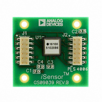
... The second level assembly uses a SnPb63/37-compatible solder composition, which has a presolder reflow thickness of approximately 0.005 inches. The pad pattern on the ADIS16100/PCBZ matches Figure 5. J1 and J2 are dual- row (pitch) connectors that work with several ribbon cable systems, including 3M Part Number 152212-0100-GB (ribbon-crimp connector) and 3M Part Number 3625/12 (ribbon cable) ...
Page 15
... OUTLINE DIMENSIONS 8.35 MAX TOP VIEW 7.00 TYP SIDE VIEW ORDERING GUIDE Model Temperature Range ADIS16100ACC −40°C to +85°C ADIS16100/PCB 5.010 BSC (4×) 2.505 BSC (8× 7.373 BSC 8.20 (2×) TYP 9 8 0.200 BOTTOM VIEW MIN (ALL SIDES) 5.20 MAX Figure 25 ...
Page 16
ADIS16100 NOTES ©2006–2009 Analog Devices, Inc. All rights reserved. Trademarks and registered trademarks are the property of their respective owners. D05461-0-6/09(D) Rev Page ...