CMA3000-D01 DEMO VTI Technologies, CMA3000-D01 DEMO Datasheet
CMA3000-D01 DEMO
Specifications of CMA3000-D01 DEMO


Related parts for CMA3000-D01 DEMO


CMA3000-D01 DEMO Summary of contents
Page 1
... CMA3000 DEMO KIT User Manual Doc.Nr. 8288400.02 ...
Page 2
... TABLE OF CONTENTS 1 Introduction .........................................................................................................................3 2 Quick start for using the CMA3000 DEMO KIT .................................................................3 3 Hardware..............................................................................................................................4 4 GUI software ........................................................................................................................4 4.1 Resetting GUI and µC ..............................................................................................................10 4.2 Uninstalling the GUI and USB driver......................................................................................10 5 Advanced data logging.....................................................................................................10 6 CMA3000 current consumption measurement with DEMO KIT ....................................12 7 USB interface board circuit diagram ...
Page 3
... CMA3000 demo runs on Windows XP and 2000, it requires USB connection for data transfer. Demo is powered from USB port. The current GUI software does not support Windows Vista. The CMA3000 demo is based on the same USB hardware PCB as the SCA3000 DEMO KIT, also the same driver can be used with all demo kits provided by VTI Technologies. ...
Page 4
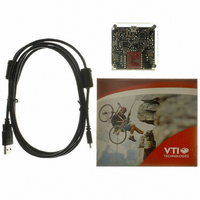
... Hardware The CMA3000 DEMO KIT USB interface board (black PWB) and CMA3000 PWB (green PWB) are shown in Figure 1. The USB interface card converts the USB interface to SPI or I CMA3000 sensor is soldered on PWB which is connected to interface board. Green led: data transfer Test points for ...
Page 5
... Current acceleration output value decimal display 10 Selected sensor type and GUI software version number. 11 Averaging ON / OFF, number of samples for averaging. 12 Measuring range (G_RANGE bit setting). 13 Pull down menu for CMA3000 operation mode & operation mode configuration. 14 Pull down menu for GUI display mode. VTI Technologies Oy www.vti. ...
Page 6
... USB serial port devices from PC and restart the GUI software. User needs to select the correct product type from PRODUCT SELECTION pop-up window (Figure 4). CMA3000-D01 is selected by default. SCROLL, continuously scrolling and resultant accelerations, see Figure 5. Acceleration is presented in [g]. User can: ...
Page 7
... When motion is detected, the operation mode is changed automatically to normal measurement mode BUBBLE LEVEL, two displays that show tilt angle, see Figure 7. Angle calculation is performed in GUI, not in CMA3000 sensor. CMA3000 sensor averaging can be enabled / disabled. Doc.Nr. 8288400.02 SCA3000 DEMO KIT User Manual to motion detection ...
Page 8
... CMA3000 Averaging can be adjusted to smoothen the demo model movements. REGISTER CONFIG display offers user access in to CMA3000 sensor internal registers. Registers can be read and written. The written data format can be changed between binary and hexadecimal by pressing the "Bits / Hex" button. ...
Page 9
... This information is needed if the CMA3000 DEMO KIT is used without the GUI software, see further details from 5. In this example the CMA3000 DEMO KIT uses COM39 serial port. RESET DEMO initialises the GUI software. The embedded MCU software version is presented also. SCROLL display opens after RESET by default ...
Page 10
... Data capturing can be stopped from: “Transfer” pull down menu → “Capture Text…” → “Stop” Macro language is used to control the CMA3000 DEMO KIT. It can be also used to configure the CMA3000 sensor. For more detailed information of macro language, please refer to “SCA3000 DEMO KIT macro language description 8259200” ...
Page 11
... Connect 1. Select COM port Figure 12. Windows HyperTerminal with CMA3000 demo info text. If the pre-configured HyperTerminal connection is not available (the CD-ROM), the HyperTerminal connection can be opened also from: → Start → Programs → Accessories → Communications → HyperTerminal The communication settings are presented in Table 2 below Table 2 ...
Page 12
... Table 3. Offset current consumption of the CMA3000 DEMO KIT HW. Serial interface SPI The offset current consumption can also be measured by measuring the voltage drop over the resistor R34 (TP5 and TP6, see Figure 16) when CMA3000 PWB is not connected to USB interface board. SCA3000 current consumption can be calculated − ⎛ ⎜ ...
Page 13
... USB interface board circuit diagram CMA3000 demo USB interface board circuit diagram is presented in following pages. Figure 14. CMA3000 DEMO KIT USB interface board circuit diagram (sheet USB). VTI Technologies Oy www.vti.fi Doc.Nr. 8288400.02 SCA3000 DEMO KIT User Manual 13/21 Rev.0.2 ...
Page 14
... Figure 15. CMA3000 DEMO KIT USB interface board circuit diagram (sheet MCU). VTI Technologies Oy www.vti.fi Doc.Nr. 8288400.02 SCA3000 DEMO KIT User Manual 14/21 Rev.0.2 ...
Page 15
... Figure 16. CMA3000 DEMO KIT USB interface board circuit diagram (sheet power). VTI Technologies Oy www.vti.fi Doc.Nr. 8288400.02 SCA3000 DEMO KIT User Manual 15/21 Rev.0.2 ...
Page 16
... USB interface board PWB layout CMA3000 DEMO KIT USB interface board PWB layout and silkscreen is presented below. Figure 17. CMA3000 DEMO KIT USB interface board PWB layout. Figure 18. CMA3000 DEMO KIT USB interface board silkscreen. VTI Technologies Oy www.vti.fi Doc.Nr. 8288400.02 SCA3000 DEMO KIT ...
Page 17
... Due to many PC environments, the interoperability can be limited. The CMA3000 DEMO KIT has been tested with DELL laptops (Latitude D600, D610, D410) and desktop PCs with Win2000 and WinXP operating system. If the CMA3000 DEMO KIT does not work properly or its operation is limited, the following items may help to sort the problems out: 1 ...
Page 18
... Checking and setting correct USB driver Latency timer value 9.1 The FTDI USB Virtual Serial Com Port driver is delivered with the CMA3000 demo kit and the same driver version can be also downloaded from VTI's website. This driver is a slightly modified version of the original FTDI's driver: the driver used with VTI's demos must have a modified Latency timer setting ...
Page 19
... VTI Technologies Oy www.vti. Doc.Nr. 8288400.02 SCA3000 DEMO KIT User Manual 19/21 Rev.0.2 ...
Page 20
... COM port numbers can be seen from Computer Management (Device Manager), see section 9.1 for instructions on opening the Device Manager. Figure 19. PC has assigned duplicate COM port numbers for two devices (LEFT), after changing the USB port there are no duplicate COM port numbers (RIGHT). VTI Technologies Oy www.vti.fi Doc.Nr. 8288400.02 SCA3000 DEMO KIT ...
Page 21
... Changing the serial bus type The MCU needs to be reset (by pressing the reset button, see Figure 1) when changing between the two available serial bus types (SPI & I CMA3000 with macros that utilize different serial bus types. 10 Document Revision History Version Date ...