HMR2300-D21-232-DEMO Honeywell Microelectronics & Precision Sensors, HMR2300-D21-232-DEMO Datasheet - Page 10
HMR2300-D21-232-DEMO
Manufacturer Part Number
HMR2300-D21-232-DEMO
Description
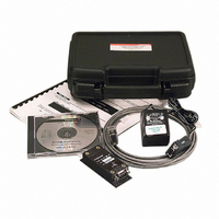
KIT DEVELOP MAGNETOMETER RS232
Manufacturer
Honeywell Microelectronics & Precision Sensors
Datasheet
1.HMR2300-D21-232-DEMO.pdf
(12 pages)
Specifications of HMR2300-D21-232-DEMO
Rohs Status
RoHS non-compliant
Sensor Type
Magnetic, Magnetometer
Sensing Range
±2g
Interface
RS-232
Sensitivity
67 microgauss
Voltage - Supply
6.5 V ~ 15 V
Embedded
No
Utilized Ic / Part
HMR2300
Silicon Manufacturer
Honeywell
Application Sub Type
Accelerometer - Three-Axis
Kit Application Type
Sensing - Motion / Vibration / Shock
Silicon Core Number
HMR2300
Kit Contents
Board
Supply Voltage
15V
Lead Free Status / RoHS Status
Other names
342-1012
HMR2300-DEMO-232
HMR2300-DEMO-232


HMR2300
OUTPUT SAMPLE RATES
The sample rate can be varied from 10 samples per second (sps) to 154 sps using the *ddR=nnn command. Each sample
contains an X, Y, and Z reading and can be outputted in either 16-bit signed binary or binary coded decimal (BCD) ASCII.
The ASCII format shows the standard numeric characters displayed on the host computer display. Some sample rates
may have restrictions on the format and baud rate used, due to transmission time constraints.
There are 7 Bytes transmitted for every reading binary format and 28 Bytes per reading in ASCII format. Transmission
times for 9600 baud are about 1 msec/Byte and for 19,200 baud are about 0.5msec/Byte. The combinations of format and
and baud rate selections are shown in the above Table. The default setting of ASCII format and 9600 baud will only
transmit correctly up to 30 sps. Note the HMR2300 will output a higher data settings, but the readings may be incorrect
and will be at alower output rate than selected.
For higher sample rates (>60 sps), it is advised that host computer settings for the terminal preferences be set so a line
feed <lf> is not appended to the sent commands. This slows down the reception of data, and it will not be able to keep up
with the incoming data stream.
INPUT SIGNAL ATTENUATION
Magnetic signals being measured will be attenuated based on the sample rate selected. The bandwidth, defined by the
3dB point, is shown in the above Table for each sample rate. The default rate of 20 sps has a bandwidth of 17Hz. The
digital filter inside the HMR2300 is the combination of a comb filter and a low pass filter. This provides a linear phase
response with a transfer function that has zeros in it.
When the 10 or 20 sps rate is used, the zeros are at the line frequencies of 50 and 60 Hz. These zeros provide better than
125 dB rejection. All multiples of the zeros extend throughout the transfer function. For example, the 10 and 20 sps rate
has zeros at 50, 60, 100, 120, 150, 180, ... Hz. The multiples of the zeros apply to all the sample rates against the stated
notch frequencies in the above Table.
COMMAND INPUT RATE
The HMR2300 limits how fast the command bytes can be recieved based on the sample rate selected. The above Table
shows the minimum time between command bytes for the HMR2300 to correctly read them. This is usually not a problem
when the user is typing the commands from the host computer. The problem could arise from an application program
outputting command bytes too quickly.
CIRCUIT DESCRIPTION
The HMR2200 Smart Digital Magnetometer contains all the basic sensors and electronics to provide digital indication of
magnetic field strength and direction. The HMR2300 has all three axis of magnetic sensors on the far end of the printed
circuit board, away from the J1 and J2 connector interfaces. The HMR2300 uses the circuit board mounting holes or the
enclosure surfaces as the reference mechanical directions. The complete HMR2300 PCB assembly consists of a mother
board, daughter board, and the 9-pin D-connector (J1).
The HMR2300 circuit starts with Honeywell HMC2003 3-Axis Magnetic Sensor Hybrid to provide X, Y, and Z axis
magnetic sensing of the earth’s field. The HMC2003 contains the AMR sensing bridge elements, a constant current
source bridge supply, three precision instrumentation amplifiers, and factory hand-selected trim resistors optimized for
performance for magnetic field gain and offset. The HMC2003 is a daughter board that plugs into the HMC2300
motherboard, and the hybrid analog voltages from each axis is into analog multiplexors and then into three 16-bit Analog
to Digital Converters (ADCs) for digitization. No calibration is necessary as the HMC2003 hybrid contains all the
compensation for the sensors, and the set/reset routine handles the temperature drift corrections. A microcontroller
integrated circuit receives the digitized magnetic field values (readings) by periodically querying the ADCs and performs
any offset corrections. This microcontroller also performs the external serial data interface and other housekeeping
functions. An onboard EEPROM integrated circuit is employed to retain necessary setup variables for best performance.
The power supply for the HMR2300 circuit is regulated +5 volt design (LM2931M) with series polarity power inputs diodes
in case of accidental polarity reversal. A charge pump circuit is used to boost the regulated voltage for the set/reset pulse
function going to the set/reset straps onboard the HMC2003. Transient protection absorbers are placed on the TD, RD,
and V+ connections to J1.
10
www.honeywell.com
Related parts for HMR2300-D21-232-DEMO
Image
Part Number
Description
Manufacturer
Datasheet
Request
R

Part Number:
Description:
Magnetometer
Manufacturer:
Honeywell Microelectronics & Precision Sensors
Part Number:
Description:
Magnetometer
Manufacturer:
Honeywell Microelectronics & Precision Sensors

Part Number:
Description:
MAGNETIC SENSORS
Manufacturer:
Honeywell Microelectronics & Precision Sensors

Part Number:
Description:
MAGNETIC SENSORS
Manufacturer:
Honeywell Microelectronics & Precision Sensors
Part Number:
Description:
MAGNETIC SENSORS
Manufacturer:
Honeywell Microelectronics & Precision Sensors
Part Number:
Description:
MAGNETIC SENSORS
Manufacturer:
Honeywell Microelectronics & Precision Sensors
Part Number:
Description:
MAGNETIC SENSORS
Manufacturer:
Honeywell Microelectronics & Precision Sensors
Datasheet:
Part Number:
Description:
MAGNETIC SENSORS
Manufacturer:
Honeywell Microelectronics & Precision Sensors

Part Number:
Description:
MAGNETIC SENSORS
Manufacturer:
Honeywell Microelectronics & Precision Sensors
Datasheet:

Part Number:
Description:
MAGNETIC SENSORS
Manufacturer:
Honeywell Microelectronics & Precision Sensors
Datasheet:

Part Number:
Description:
SENSOR LINEAR MAGN 1 AXIS 8-SIP
Manufacturer:
Honeywell Microelectronics & Precision Sensors
Datasheet:

Part Number:
Description:
SENSOR MAGN 2 AXIS 10-MSOP
Manufacturer:
Honeywell Microelectronics & Precision Sensors
Datasheet:

Part Number:
Description:
Magnetic Sensor
Manufacturer:
Honeywell Microelectronics & Precision Sensors
Datasheet:

Part Number:
Description:
Magnetic Sensor
Manufacturer:
Honeywell Microelectronics & Precision Sensors
Datasheet:

Part Number:
Description:
IC, MAGNETO RESISTIVE SENSOR, LCC-16
Manufacturer:
Honeywell Microelectronics & Precision Sensors
Datasheet: