ADIS16265/PCBZ Analog Devices Inc, ADIS16265/PCBZ Datasheet - Page 11

ADIS16265/PCBZ
Manufacturer Part Number
ADIS16265/PCBZ
Description
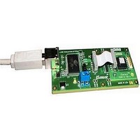
BOARD EVALUATION FOR ADIS16265
Manufacturer
Analog Devices Inc
Series
iMEMS®, iSensor™r
Datasheet
1.ADIS16260PCBZ.pdf
(20 pages)
Specifications of ADIS16265/PCBZ
Sensor Type
Gyroscope, 1 Axis
Sensing Range
±80°/sec, ±160°/sec, ±320°/sec
Sensitivity
±0.2%
Embedded
No
Utilized Ic / Part
ADIS16265
Silicon Manufacturer
Analog Devices
Application Sub Type
Angular Rate Sensor / Gyroscope
Kit Application Type
Sensing - Motion / Vibration / Shock
Silicon Core Number
ADIS16265
Lead Free Status / RoHS Status
Lead free / RoHS compliant by exemption
Voltage - Supply
-
Interface
-
Lead Free Status / RoHS Status
Lead free / RoHS compliant by exemption
SPI WRITE COMMANDS
Master processors write to the control registers, one byte
at a time, using the bit sequence shown in Figure 11. Some
configurations require writing both bytes to a register, which
takes two separate 16-bit sequences, whereas others require
only one byte. The programmable registers in Table 7 provide
controls for optimizing sensor operation and for starting vari-
ous automated functions. For example, to start an automatic
bias null sequence, set GLOB_CMD[0] = 1 by writing 0xBE01
to the SPI transmit register of the master processor, which feeds
the DIN line. The process starts immediately after the last bit
clocks into DIN (16
SCLK
DIN
CS
Figure 12. SPI Sequence for Autonull (DIN = 0xBE01)
SCLK
DIN
CS
th
DIN = 0x0400 PRODUCES GYRO_OUT CONTENTS ON
SCLK rising edge).
DOUT DURING THE NEXT SPI SEGMENT
SPI SEGMENT 1
Figure 13. Example SPI Read Sequence (±320°/sec Range Setting)
Rev. B | Page 11 of 20
DOUT
SPI READ COMMANDS
Reading data through the SPI requires two consecutive 16-bit
sequences, separated by an appropriate stall time (see Figure 2).
The first sequence transmits the read command and address on
DIN, and the second receives the resulting data from DOUT. The
7-bit register address can represent either the upper or lower byte
address for the target register. For example, when reading the
GYRO_OUT register, the address can be either 0x04 or 0x05.
Figure 13 provides a full-duplex mode example of reading the
GYRO_OUT register. In addition, the second SPI segment sets
the device up to read TEMP_OUT on the following SPI segment
(not shown in Figure 13).
DOUT = 0x822B = 21.9047°/sec, NEW DATA, NO ALARM
SPI SEGMENT 2
ADIS16260/ADIS16265


