ADIS16265/PCBZ Analog Devices Inc, ADIS16265/PCBZ Datasheet - Page 17
ADIS16265/PCBZ
Manufacturer Part Number
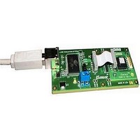
ADIS16265/PCBZ
Description
BOARD EVALUATION FOR ADIS16265
Manufacturer
Analog Devices Inc
Series
iMEMS®, iSensor™r
Datasheet
1.ADIS16260PCBZ.pdf
(20 pages)
Specifications of ADIS16265/PCBZ
Sensor Type
Gyroscope, 1 Axis
Sensing Range
±80°/sec, ±160°/sec, ±320°/sec
Sensitivity
±0.2%
Embedded
No
Utilized Ic / Part
ADIS16265
Silicon Manufacturer
Analog Devices
Application Sub Type
Angular Rate Sensor / Gyroscope
Kit Application Type
Sensing - Motion / Vibration / Shock
Silicon Core Number
ADIS16265
Lead Free Status / RoHS Status
Lead free / RoHS compliant by exemption
Voltage - Supply
-
Interface
-
Lead Free Status / RoHS Status
Lead free / RoHS compliant by exemption


Table 28. ALM_CTRL Bit Descriptions
Bits
[15]
[14:12]
[11]
[10:8]
[7:5]
[4]
[3]
[2]
[1]
[0]
Table 29. Alarm Configuration Example 1
DIN
0xA922,
0xA817
0xA181,
0xA000
0xA33F,
0xA200
Description (Default = 0x0000)
Rate-of-change enable for Alarm 2
(1 = rate of change, 0 = static level).
Alarm 2 source selection.
000 = disable.
001 = power supply output.
010 = gyroscope output.
011 = not used.
100 = not used.
101 = auxiliary ADC input.
110 = temperature output.
111 = not used.
Rate-of-change enable for Alarm 1
(1 = rate of change, 0 = static level).
Alarm 1 source selection (same as for Alarm 2).
Not used.
Comparison data filter setting
(1 = filtered data, 0 = unfiltered data).
Not used.
Alarm output enable
(1 = enabled, 0 = disabled).
Alarm output polarity
(1 = active high, 0 = active low).
Alarm output line select
(1 = DIO2, 0 = DIO1).
Description
ALM_CTRL = 0x2217.
Alarm 1 input = GYRO_OUT.
Alarm 2 input = GYRO_OUT.
Static level comparison, filtered data.
DIO2 output indicator, positive polarity.
ALM_MAG1 = 0x8100.
Alarm 1 is true if GYRO_OUT > +18.755°/sec.
ALM_MAG2 = 0x3F00.
Alarm 2 is true if GYRO_OUT < −18.755°/sec.
Rev. B | Page 17 of 20
Table 30. Alarm Configuration Example 2
DIN
0xA9AA,
0xA804
0xB601
0xA40A
0xA60A
0xA181,
0xA000
0xA30F,
0xA200
PRODUCT IDENTIFICATION
Table 31 provides a summary of the registers that identify
the product: PROD_ID, which identifies the product type;
LOT_ID1 and LOT_ID2, the 32-bit lot identification code;
and SERIAL_NUM, which displays the 16-bit serial number.
All four registers are two bytes in length.
Table 31. Identification Registers
Register Name
LOT_ID1
LOT_ID2
PROD_ID
SERIAL_NUM
Description
ALM_CTRL = 0xAA04.
Alarm 1 input = GYRO_OUT.
Alarm 2 input = GYRO_OUT.
Rate-of-change comparison, unfiltered data.
DIO1 output indicator, negative polarity.
SMPL_PRD = 0x0001.
Sample rate = 256 SPS.
ALM_SMPL1[7:0] = 0x000A.
Alarm 1 rate-of-change period = 3.906 ms.
ALM_SMPL2[7:0] = 0x000A.
Alarm 2 rate-of-change period = 3.906 ms.
ALM_MAG1 = 0x8100.
Alarm 1 is true if GYRO_OUT changes more than
18.755°/sec over a period of 3.906 ms.
ALM_MAG2 = 0x0F00.
Alarm 2 is true if GYRO_OUT changes less than
18.755°/sec over a period of 3.906 ms.
Address
0x52
0x54
0x56
0x58
ADIS16260/ADIS16265
Description
Lot Identification Code 1
Lot Identification Code 2
Product identification = 0x3F89 or
0x3F84
(0x3F89 = 16,265 decimal; 0x3F84 =
16,260 decimal)
Serial number
Related parts for ADIS16265/PCBZ
Image
Part Number
Description
Manufacturer
Datasheet
Request
R

Part Number:
Description:
±1.7g Dual-Axis IMEMS Accelerometer Evaluation Board
Manufacturer:
Analog Devices Inc
Datasheet:

Part Number:
Description:
Inertial Sensor Evaluation System
Manufacturer:
Analog Devices Inc
Datasheet:
Part Number:
Description:
Manufacturer:
Analog Devices Inc
Datasheet:
Part Number:
Description:
Manufacturer:
Analog Devices Inc
Datasheet:
Part Number:
Description:
Manufacturer:
Analog Devices Inc
Datasheet:
Part Number:
Description:
Manufacturer:
Analog Devices Inc
Datasheet:
Part Number:
Description:
Manufacturer:
Analog Devices Inc
Datasheet:
Part Number:
Description:
Manufacturer:
Analog Devices Inc
Datasheet:
Part Number:
Description:
Manufacturer:
Analog Devices Inc
Datasheet:
Part Number:
Description:
Manufacturer:
Analog Devices Inc
Datasheet:
Part Number:
Description:
Manufacturer:
Analog Devices Inc
Datasheet:
Part Number:
Description:
Manufacturer:
Analog Devices Inc
Datasheet:
Part Number:
Description:
Manufacturer:
Analog Devices Inc
Datasheet: