DV164122 Microchip Technology, DV164122 Datasheet - Page 113
DV164122
Manufacturer Part Number
DV164122
Description
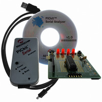
ANALYZER SRL PICKIT W/DEMO BOARD
Manufacturer
Microchip Technology
Series
PICkit™r
Type
MCUr
Specifications of DV164122
Contents
PICkit™ Serial Analyzer, 28-pin Demo Board, USB Cable, and Software with Documentation CD
Processor To Be Evaluated
PIC16F886
Interface Type
USB
Silicon Manufacturer
Microchip
Kit Application Type
Interface
Application Sub Type
USB
Silicon Family Name
PIC16F
Kit Contents
PICkit Serial Analyzer, Demo Board, USB Cable, Software
Rohs Compliant
Yes
Lead Free Status / RoHS Status
Not applicable / Not applicable
For Use With/related Products
PIC16F886
For Use With
PKSERIAL-SPI1 - BOARD DEMO PICKIT SERIAL SPIPKSERIAL-I2C1 - BOARD DEMO PICKIT SERIAL I2C
Lead Free Status / Rohs Status
Lead free / RoHS Compliant
Other names
Q3260228
Available stocks
Company
Part Number
Manufacturer
Quantity
Price
Company:

Part Number:
DV164122
Manufacturer:
Microchip Technology
Quantity:
135
Company:
Part Number:
DV164122
Manufacturer:
MICROCHIP
Quantity:
12 000


B.1
B.2
B.3
B.4
© 2007 Microchip Technology Inc.
Appendix B. 28-Pin Demo Board I
INTRODUCTION
HIGHLIGHTS
HARDWARE
FIRMWARE
The 28-Pin Demo Board I
PICkit™ Serial Analyzer using the I
the I
Demo board is programmed to emulate an I
EEPROM.
This chapter discusses:
• Hardware
• Firmware
• I
• Slave Devices
• Functions
The 28-Pin Demo Board (DM164120-3) is populated with and configured for:
• PIC16F886 configured using the 8 MHz internal clock
• 32 kHz Tuning Fork Crystal connected to Timer1 Low-power Oscillator
• Four LEDs (DS1 through DS4) connected to RB0 through RB3
• Potentiometer (RP1) connected to RA0/AN0
• Push button (SW1) connected to RE3/MCLR
For more information about the 28-Pin Demo Board hardware, see the 28-Pin Demo
Board User’s Guide (DS41301).
The demo program source code and *.hex file can be found on the PICkit Serial
CD-ROM at D:\28-pin Demo Board\Firmware\.
The firmware is structured as multiple ‘modules’ representing functional components.
Each module contains, at minimum, an “initialization” routine (MODULE_INIT) and a
“service” routine (MODULE_SVC). Each initialization routine is called from MAIN once
on Reset. Each Interrupt Service Routine is called sequentially and continuously from
the MAIN Idle loop. Interrupt Service Routine is provided for the I
other modules are serviced in turn from the MAIN ‘Idle loop’.
2
C Communications
2
C Master and the 28-Pin Demo Board will be the I
PICkit™ SERIAL ANALYZER USER’S
2
C™ demonstration firmware communicates with the
2
2
C serial protocol. The PICkit Serial Analyzer will be
C™ Demonstration Firmware
2
C Real-Time Clock (RTC) and Serial
2
C Slave device. The 28-Pin
2
C module only. All
DS51647A-page 107
GUIDE
Related parts for DV164122
Image
Part Number
Description
Manufacturer
Datasheet
Request
R

Part Number:
Description:
Manufacturer:
Microchip Technology Inc.
Datasheet:
Part Number:
Description:
Manufacturer:
Microchip Technology Inc.
Datasheet:
Part Number:
Description:
Manufacturer:
Microchip Technology Inc.
Datasheet:
Part Number:
Description:
Manufacturer:
Microchip Technology Inc.
Datasheet:
Part Number:
Description:
Manufacturer:
Microchip Technology Inc.
Datasheet:
Part Number:
Description:
Manufacturer:
Microchip Technology Inc.
Datasheet:
Part Number:
Description:
Manufacturer:
Microchip Technology Inc.
Datasheet:
Part Number:
Description:
Manufacturer:
Microchip Technology Inc.
Datasheet: