DV164122 Microchip Technology, DV164122 Datasheet - Page 114
DV164122
Manufacturer Part Number
DV164122
Description
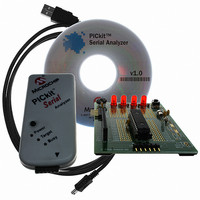
ANALYZER SRL PICKIT W/DEMO BOARD
Manufacturer
Microchip Technology
Series
PICkit™r
Type
MCUr
Specifications of DV164122
Contents
PICkit™ Serial Analyzer, 28-pin Demo Board, USB Cable, and Software with Documentation CD
Processor To Be Evaluated
PIC16F886
Interface Type
USB
Silicon Manufacturer
Microchip
Kit Application Type
Interface
Application Sub Type
USB
Silicon Family Name
PIC16F
Kit Contents
PICkit Serial Analyzer, Demo Board, USB Cable, Software
Rohs Compliant
Yes
Lead Free Status / RoHS Status
Not applicable / Not applicable
For Use With/related Products
PIC16F886
For Use With
PKSERIAL-SPI1 - BOARD DEMO PICKIT SERIAL SPIPKSERIAL-I2C1 - BOARD DEMO PICKIT SERIAL I2C
Lead Free Status / Rohs Status
Lead free / RoHS Compliant
Other names
Q3260228
Available stocks
Company
Part Number
Manufacturer
Quantity
Price
Company:

Part Number:
DV164122
Manufacturer:
Microchip Technology
Quantity:
135
Company:
Part Number:
DV164122
Manufacturer:
MICROCHIP
Quantity:
12 000


PICkit™ Serial Analyzer User’s Guide
B.5
DS51647A-page 108
I
2
C COMMUNICATIONS
TABLE B-1:
B.5.1
The 28-Pin Demo Board I
TABLE B-2:
All devices (slave addresses) respond to the I
device supports a fixed number of word addresses (see section B.6 Slave Devices
below). The word address is automatically incremented during a transaction for
sequential access of the device registers. If the word address is incremented beyond
the end of the supported address range, the address will “wrap”.
B.5.2
Figure B-1 shows the Master and Slave legend used for Figures B-2 through B-4.
FIGURE B-1:
Write Byte(s) – This transaction is used to write one or more bytes. The maximum
number of bytes is slave-dependant.
adc.asm
device.asm
ee_util.asm
exec.asm
i2c_slave_pksd.asm
led.asm
main.asm
pksi.asm
rtc.asm
timer0.asm
timer1.asm
0xA2
0xA8
0xAA
ADDR
MODULE
Overview
Protocols
FIRMWARE MODULES
DEVICE SLAVE ADDRESSES
RTC
EEPROM
EXEC
MASTER/SLAVE DEVICE LEGEND
NAME
ADC service – measuring channel AN0, connected to potentiometer
RP1, and post results to register in shared memory
Basic device (microcontroller) configuration
EEPROM Read/Write routines
“Executive” feature set – provides functionality for test and demon-
stration of PICkit™ Serial Analyzer and 28-Pin Demo Board
I
0xA2: Real-Time Clock (RTC)
0xA8: EEPROM
0xAA: Executive (EXEC)
LED management, set/reset LEDs per state register
Initialization, Idle loop and Interrupt Service Routine context
management
Monitor PICkit Serial Analyzer interface I/O pins – post results to state
register
I
register-based I/O
Utilizes TMR0 as a source for multiple “soft” timers
Utilizes TMR1 with external 32 kHz crystal for RTC 1-second ‘ticks’
2
2
C™ service for three slave devices:
C™ device: real-time clock emulation maintains 16 locations for
2
C™ Demo responds to three I
Master
Device emulation: Real-Time Clock
Device emulation: EEPROM
Supervisory features
2
C protocols described below. Each slave
DESCRIPTION
Slave
DESCRIPTION
2
C slave addresses:
© 2007 Microchip Technology Inc.
Related parts for DV164122
Image
Part Number
Description
Manufacturer
Datasheet
Request
R

Part Number:
Description:
Manufacturer:
Microchip Technology Inc.
Datasheet:
Part Number:
Description:
Manufacturer:
Microchip Technology Inc.
Datasheet:
Part Number:
Description:
Manufacturer:
Microchip Technology Inc.
Datasheet:
Part Number:
Description:
Manufacturer:
Microchip Technology Inc.
Datasheet:
Part Number:
Description:
Manufacturer:
Microchip Technology Inc.
Datasheet:
Part Number:
Description:
Manufacturer:
Microchip Technology Inc.
Datasheet:
Part Number:
Description:
Manufacturer:
Microchip Technology Inc.
Datasheet:
Part Number:
Description:
Manufacturer:
Microchip Technology Inc.
Datasheet: