ATSTK600 Atmel, ATSTK600 Datasheet - Page 44
ATSTK600
Manufacturer Part Number
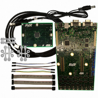
ATSTK600
Description
DEV KIT FOR AVR/AVR32
Manufacturer
Atmel
Series
AVR®r
Type
MCUr
Specifications of ATSTK600
Processor To Be Evaluated
AVR and AVR32
Data Bus Width
8 bit
Interface Type
RS-232, USB
Silicon Manufacturer
Atmel
Core Architecture
AVR
Core Sub-architecture
AVR UC3
Silicon Core Number
STK600
Silicon Family Name
AVR
Kit Contents
Board
Rohs Compliant
Yes
For Use With/related Products
Atmel AVR Devices
For Use With
ATSTK600-ATTINY10 - STK600-ATTINY10 SOCKET PACKAGE
Lead Free Status / RoHS Status
Lead free / RoHS Compliant
Contents
-
Lead Free Status / Rohs Status
Lead free / RoHS Compliant
Available stocks
Company
Part Number
Manufacturer
Quantity
Price
Company:

Part Number:
ATSTK600
Manufacturer:
Atmel
Quantity:
135
Company:
Part Number:
ATSTK600-ATTINY10
Manufacturer:
Atmel
Quantity:
135
Company:
Part Number:
ATSTK600-DIP40
Manufacturer:
Atmel
Quantity:
135
Company:
Part Number:
ATSTK600-RC14
Manufacturer:
Atmel
Quantity:
135
Company:
Part Number:
ATSTK600-RC15
Manufacturer:
Atmel
Quantity:
135


11.21 PARAM_BOARD_ID_STATUS
11.22 PARAM_RESET
11.23 PARAM_RESET_POLARITY
11.24 PARAM_JTAG_ALLOW_FULL_PAGE_STREAM
11.25 PARAM_JTAG_EEPROM_PAGE_SIZE
11.26 PARAM2_JTAG_FLASH_PAGE_SIZE
11.27 PARAM2_JTAG_FLASH_SIZE_H
11.28 PARAM2_JTAG_FLASH_SIZE_L
11.29 PARAM_JTAG_DAISY_BITS_BEFORE
44
AVR079
0x00 = OK
0x01 = BoardID mismatch (VTG set to 0V)
0x02 = BoardID changed while power on STK600 (VTG set to 0V)
Used to set the reset line high or low. Will only work when the board is idle.
If used when the kit is in programming mode the parameter will be ignored.
For backward compatability with the STK500, this parameter sets the reset polarity.
Boolean value to indicate if the target MCU supports streaming a full flash page of
data, or if each byte must be followed by a return to idle (jtag state).
XML:AVRPART\ICE_SETTINGS\JTAGICEmkII\ucAllowFullPageBitstream
Used to set the EEprom page size (in bytes)
Used to set the flash page size (in bytes)
Used to set the flash size (in bytes). As this value can extend 0xffff (64k) the value is
split into two parameter registers.
See PARAM2_JTAG_FLASH_SIZE_H
When the target MCU is part of a JTAG daisy chain the STK600 must know how
many
PARAM_JTAG_DAISY_BITS_BEFORE and AFTER values specifies how many
instruction register bits to skip.
In the JTAG data phase all non targeted devices have the SKIP register selected. The
SKIP register is one bit. The PARAM_JTAG_DAISY_UNITS_BEFORE and AFTER
parameters specify the number of devices before and after the target device, and
hence the total SKIP register length to ignore.
Example: If the targeted AVR is placed second, in a 4 device chain with instruction
register lengths 2, 2 and 5 respectively,
Table 11-5.
Name
bits
it
should
skip
before
Value
and
after
the
target.
8133A-AVR-04/08
The
Related parts for ATSTK600
Image
Part Number
Description
Manufacturer
Datasheet
Request
R

Part Number:
Description:
INTERVAL AND WIPE/WASH WIPER CONTROL IC WITH DELAY
Manufacturer:
ATMEL Corporation
Datasheet:
Part Number:
Description:
Low-Voltage Voice-Switched IC for Hands-Free Operation
Manufacturer:
ATMEL Corporation
Datasheet:
Part Number:
Description:
MONOLITHIC INTEGRATED FEATUREPHONE CIRCUIT
Manufacturer:
ATMEL Corporation
Datasheet:
Part Number:
Description:
AM-FM Receiver IC U4255BM-M
Manufacturer:
ATMEL Corporation
Datasheet:
Part Number:
Description:
Monolithic Integrated Feature Phone Circuit
Manufacturer:
ATMEL Corporation
Datasheet:
Part Number:
Description:
Multistandard Video-IF and Quasi Parallel Sound Processing
Manufacturer:
ATMEL Corporation
Datasheet:
Part Number:
Description:
High-performance EE PLD
Manufacturer:
ATMEL Corporation
Datasheet:
Part Number:
Description:
8-bit Flash Microcontroller
Manufacturer:
ATMEL Corporation
Datasheet:
Part Number:
Description:
2-Wire Serial EEPROM
Manufacturer:
ATMEL Corporation
Datasheet:
Part Number:
Description:
U6046BREAR WINDOW HEATING TIMER / LONG-TERM TIMER
Manufacturer:
ATMEL Corporation
Datasheet: