USB-100 Fujitsu Semiconductor America Inc, USB-100 Datasheet
USB-100
Specifications of USB-100


Related parts for USB-100


USB-100 Summary of contents
Page 1
... FR80 Family 32-BIT MICROCONTROLLER MB91F662 bits pot black USB board User's Manual ...
Page 2
Disclaimer and Legal Notice The contents of this document are subject to change without a prior notice, thus ask our sales division about the latest one. The descriptions of functions and application circuit examples in this document are provided solely ...
Page 3
Control Law of Japan and US export control laws. The company names and product names mentioned in this document are a trademark or registered trademark of their respective owners. Copyright(c) 2008 FUJITSU MICROELECTRONICS LIMITED all rights reserved 2 ...
Page 4
Revision History Revisions Date Version 1.0 2008/09/25 Description First issue 3 ...
Page 5
... Plug .............................................................................................................................. 57 4.5 Transfer rate................................................................................................................. 58 4.6 Transfer rate detection ................................................................................................. 58 4.7 Transfer methods ......................................................................................................... 59 4.8 Configuration of a device ............................................................................................. 60 4.9 Enumeration ................................................................................................................. 61 4.10 Device class ................................................................................................................. 64 5 Let's make a USB mouse .................................................................................................... 65 5.1 Overview of the USB sample program......................................................................... 65 5.2 Overview of USB communications flow ....................................................................... 68 5.2.1 Overview of USB communications flow................................................................ 68 4 ...
Page 6
... Device request (PC -> Starter kit)......................................................................... 72 5.2.3 Descriptor (PC <- Starter kit) ................................................................................ 75 5.3 Sample program sequence .......................................................................................... 80 5.3.1 Main routine .......................................................................................................... 80 5.3.2 USB initialization process ..................................................................................... 82 5.3.3 USB interrupt processing...................................................................................... 83 5.3.4 EP0 data receive process..................................................................................... 85 5.3.5 Setup command receive process ......................................................................... 86 5.3.6 Switch operation detection process...................................................................... 88 5 ...
Page 7
Installation and usage of the PC writer .............................................................................. 129 4 Monitor debugger............................................................................................................... 138 4.1 Explanation of the monitor debugger ......................................................................... 138 4.2 Resources used by monitor debugger ....................................................................... 139 4.3 Memory map with monitor debugger installed ........................................................... 140 4.4 ...
Page 8
... This starter kit is a USB microcontroller training kit equipped with Fujitsu's microcontroller MB91F662 (certified USB*). This starter kit provides an easy-to-understand training system for USB microcontrollers, and is intended for students who need to know "What is a USB?", "How is it used?", and "What is it used for?" ...
Page 9
Contact For inquiries about this starter kit, contact the following address. Zip code: 105-8420 2-5-3 Nishi-Shinbashi, Minatoku, Tokyo E-mail: pd-bitspot@tsuzuki-densan.co.jp bits pot URL: http://www.tsuzuki-densan.co.jp/bitspot/ 8 ...
Page 10
... GCM31CR71E475KA40L (4.7uF), GCM32ER71E106KA42L(10uF), GCM155R11A473KA01D (47000pF), GCM1552C1H471JA0D (470pF), GCM1552C1H470JA0D (47pF), GCM155R11E103KA01D (10000pF), GCM155R11E223KA01D (22000pF) INTERFACE Co., Ltd. Provided free of charge: USB control firmware KYOWA ELECTRONIC INSTRUMENTS CO., LTD. Provided at a nominal cost: Strain gauge: KFG-5-350-C1-11L1M2R @@@ TDK Corporation Provided free of charge: Chip NTC Thermistor: NTCG164BH103J Chip beads: MPZ2012S300AT @ ...
Page 11
Fujitsu Microelectronics Limited Provided free of charge: Microcontroller MB91F662 Sensor Conditioner IC MB42M131 FRAM MB85RS256 Power Voltage Monitoring IC with Watchdog Timer Integrated Development Environment SOFTUNE Workbench Sample programs MB3793-30A 10 ...
Page 12
... Checking package contents Make sure your package contains all items listed in Table 1.1-1, Starter kit package contents. Figure 1.1-1 shows a photo of the contents. Name (1) Main board (2) USB A to Mini-B cable (1) Main board Table 1.1-1 Starter kit package contents Qty. Specifications/Remarks 1 FUJITSU ...
Page 13
... Required software The software required in order to operate the starter kit are listed in Table 1.2- the online software purchasing website for bits pot black and download the required software. Website for purchasing bit pot black, TSUZUKI DENSAN Co., Ltd. (Japanese) http://emono-tsuzuki.jp/SHOP/USB-100.html Name 1 SOFTUNE ...
Page 14
The sample programs are organized as shown in the diagram below. (The sample program provided by INTERFACE Co., Ltd., is beyond the scope of this manual.) [bits_pot_black_e] [sample_program] sample_program_e.zip [monitor] moitor.mhx [manual] users_manual_e.pdf schematic.pdf [software] [SOFTUNE] FR_ProPack_Rev600010-BV-ComExpansion.zip [PC_writer] MB91F662_setup.exe : ...
Page 15
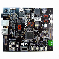
... Figure 1.4-1 shows the external appearance of the starter kit board, and Table 1.4-1 lists the major components. (2) FRAM (12) USB B connector (13) USB A connector (6) Pushbutton SW Figure 1.4-1 External appearance of the starter kit board (11) USB Mini-B connector (7) Pushbutton SW (9) Slider SW (for analog input) (1) Main MCU 14 (10) Slider SW (8) Pushbutton SW (3) Humidity sensor ...
Page 16
... Slider SW Controls mode selection of the main microcontroller. (11) USB Mini-B Connects the PC and main microcontroller with connector the USB B to Mini-B cable. Used for debugging serial communications. (12) USB B connector Used to control the USB mouse operation. (13) USB A connector Used when operating the microcontroller as a host ...
Page 17
Starter kit parts Table 1.5-1 lists the parts in the starter kit. Part number C1,C2,C4,C6,C9, C10,C12,C13, C18,C19,C37, Monolithic ceramic capacitor C36,C56,C58, C60,C61 C3,C5 Monolithic ceramic capacitor C7,C11,C54,C55 Monolithic ceramic capacitor C17,C32,C33 Monolithic ceramic capacitor C14,C15,C16 Monolithic ceramic capacitor C20,C21,C22, ...
Page 18
Part number P_SW1,P_SW2, P_SW3,P_SW4, P_SW5,P_SW6, Push switch P_SW7,P_SW8, P_SW9,P_SW10 Q1 Digital transistor R1,R3,R4,R5,R7,R8, R27,R28,R29,R30, R31,R32,R33,R34, Chip resistor R42,R44,R45,R49, R70,R76,R89 R9,R10,R17,R78, R79,R84,R85, Chip resistor R86,R87,R88 R11,R13,R15,R26,R77 Chip resistor R12,R14,R16 Chip resistor R18,R21,R22,R23, Chip resistor R25,R39,R72,R75 R19,R24 Chip network resistor R20 Chip ...
Page 19
... Terminal block U7,U9 7-SEG LED U8 SMD piezoelectric sounder U10 Humidity sensor U11 USB_A connector U13 Regulator U14 USB to serial converter U15 USB Mini-B connector U16 USB_B connector Power Voltage Monitoring IC with U18 Watchdog Timer U22 DC jack U23 USB power switch VR1 ...
Page 20
... USB FUNC 3 External power External supply (5V) Remarks Draws bus power from the PC via the USB A to Mini-B cable. Draws bus power from the PC via the USB A to USB B cable. Draws power from an AC adapter. (AC adapter not included with kit.) < Typical AC adapter models> ...
Page 21
... Never change the power supply selector to External when the external power supply (5V) is not supplying power. • Do not change the power supply selector switch to USB FUNC when the USB B connector is disconnected. • Do not change the power supply selector switch to USB Mini-B when the USB Mini-B connector is disconnected ...
Page 22
... Install the software required to operate this starter kit to your PC. Be sure to download the required software before starting the installation process. The setup procedures are as follows. Setup procedures: - Installation of the integrated development environment SOFTUNE (bits pot dedicated version) (Refer to Section 2.1) - Installation of USB drivers (Refer to Section 2.2) 21 ...
Page 23
Installing the integrated development environment SOFTUNE (bits pot dedicated version) What is SOFTUNE? SOFTUNE is the integrated development environment (IDE) for developing programs and evaluating FUJITSU Microcontrollers. Developing programs for microcontrollers commonly used in embedded devices is a repetitive ...
Page 24
Click "Next". Click "Next". 23 ...
Page 25
If you agree with the usage license, click "Yes". Click "Next". 24 ...
Page 26
Click "Next". Leave the destination folder at the default, "C:¥Softune6". Confirm the components selected for installation. "Customize Bar" is not checked by default so place a check in it. 25 ...
Page 27
Verify the details of the installation are acceptable. If there are no problems, click "Next". Wait for the installation to complete. 26 ...
Page 28
Click the "Finish" button to complete the installation of SOFTUNE. 27 ...
Page 29
... Installing the USB driver The starter kit is equipped with a USB-to-serial converter IC (made by FTDI) between the USB Mini-B connector and microcontroller. This USB driver must be downloaded from the FTDI website. Download the driver software to a folder on your PC from the URL listed below beforehand. ...
Page 30
... Once the driver has been downloaded and unpacked, the starter kit is ready to be connected to the PC using the supplied USB cable. However, before doing so, check the switch settings on the board. Figure 2.2-1 and Table 2.2-1 show the switch settings to use when installing the USB driver. (1) Set to " ...
Page 31
... After setting the switches on the board, connect the PC and board using the USB A to Mini-B cable supplied with the starter kit. Do not connect the cable to "USB FUNC" or "USB HOST". When you connect the board to the PC, the PC will recognize the new hardware and display messages prompting you to install the driver ...
Page 32
This procedure will explain how to install the driver software previously downloaded instead of connecting to Windows Update. Select "Install from a list or specific location (Advanced)", and click "Next". Click "Browse" and specify the folder "CDM 2.04.06 WHQL Certified" ...
Page 33
... Wait for the "USB Serial Converter" installation to complete. Click "Finish" to complete the installation of "USB Serial Converter". 32 ...
Page 34
... Next, install the "USB Serial Port". Select "Install from a list or specific location (Advanced)", and click "Next". Click "Browse" and specify the folder "CDM 2.04.06 WHQL Certified" downloaded earlier, then click "Next". 33 ...
Page 35
... Wait for the "USB Serial Port" installation to complete. Click "Finish" to complete the installation of "USB Serial Port". This completes the installation of the USB driver. 34 ...
Page 36
... Launching SOFTUNE and using the monitor debugger 3.1 Launching SOFTUNE After installing SOFTUNE and the USB driver, launch SOFTUNE by clicking Windows [Start] - [All Programs] - [SOFTUNE V6] - [FR Family SOFTUNE Workbench]. Figure 3.1-1 shows the screen layout when SOFTUNE starts up. Menu bar Project window Figure 3 ...
Page 37
Menu bar Tool bar Project window Edit window Output window Status bar !! HINT !! You can move the position of the tool bars and resize windows freely to match your preferences. Project window Contains menu items for the SOFTUNE ...
Page 38
... Table 3.1-1 List of projects in sample.wsp Project name io_mb91660 CPU register definitions file sample_LED 7-segment LED program sample_skeleton For creating new programs sample_USB sample_humidity sample_strain_gauge Electronic scale sample_FRAM_SPI Counter using FRAM Description ― Chapter 2 (this chapter) Appendix USB mouse Chapter 5 Hygrometer Chapter 9 Chapter 7 Chapter 11 37 Reference ...
Page 39
In order to confirm everything has been setup properly, we will use the sample program "sample_LED" to flash the letters "FJ" on the 7-segment LED on the starter kit board. Make sure "sample_LED.abs – “sample_LED.prj”[Debug]” is set as the active ...
Page 40
Next, we will compile the program. Click the "Build" button to compile, and verify there were no errors in the compilation results in the output window. If the compilation was successful, proceed to setup and launch the monitor debugger. "Build" ...
Page 41
Setting and launching the monitor debugger Explanation of the monitor debugger The monitor debugger allows developers to debug the program loaded on a production microcontroller with built-in FLASH memory. Installing a monitor program with the application program provides access ...
Page 42
The setup wizard for the debugger starts up. Click "Next". Select "Monitor Debugger" for debugger type. Click "Next". 41 ...
Page 43
Select "RS" as the Type and specify the COM port the board is connected to. Leave the baud rate at "256000". Click "Next". Refer to Appendix 2 in this manual to verify COM ports. 42 ...
Page 44
Click "Next". Make sure the option "Auto load when starting debug." has a check in it, and that the batch file for "Before" is set to "FshLdWrt.prc". "FshLdWrt.prc" batch file for writing user programs to the FLASH memory ...
Page 45
... Silk printing on board Setting SW6 USB Mini-B SW1 RUN SW2 Debug SW3 FUNC To USB Mini-B connector Remarks Enables USB Mini-B. Operates the microcontroller in user mode. Operates the microcontroller in debug mode. Uses the microcontroller's USB FUNCTION. 44 Always press the Reset SW before launching the debugger. ...
Page 46
... If the settings were made correctly, the batch file for "Before " in the setup wizard will run. When the dialog bar is showing, the program is being downloaded to the FLASH memory on the microcontroller. Do not disconnect the USB cable from the board or the PC during the download. 45 ...
Page 47
... If the debugger does not launch Check the following. 1. Board settings. • Is the USB cable properly connected to the board and PC? • Are the switches on the board set properly? 2. Setup wizard settings. • Are the COM port and baud rate settings correct both 1 and 2 are correct but the debugger still does not launch, the monitor program may be corrupt ...
Page 48
Using the monitor debugger The debugger will launch when the download to the FLASH memory on the microcontroller completes. The debugger should be pointing to the starting address of the user program. 47 ...
Page 49
Run the program by clicking the "Run continuously" button in the upper left of the SOFTUNE window. 48 ...
Page 50
Execution is successful if the letters "FJ" appear flashing on the 7-segment LED. 49 ...
Page 51
To stop program execution, press the "DEBUG STOP" button on the board. The flashing "FJ" will stop when the DEBUG STOP button is depressed. Depending on the timing, the program may stop with FJ still showing. To resume program execution, ...
Page 52
Function (1) Run Continuously Executes program continuously from the current position in the program counter (PC). (2) Step In Executes the step and moves the PC to the address of the next instruction and stops. (3) Step ...
Page 53
Make Compiles/assembles only the source files that have changed. Then, links all objects and libraries to generate the target program. (6) Build Compiles/assembles all source files registered in the project, whether they have changed or not, then links all ...
Page 54
Memory window (12) Register window (13) Watch window (11) (12) Shows the memory contents during debug. If the window is not showing, click "View" - "Memory" to show it. Shows the register contents during debug. If the window is ...
Page 55
Exiting monitor debug To end debugging, always stop the program execution by pressing the DEBUG STOP button on the board . Then, click "Debug" - "End Debug". Refer to the monitor debugger limitations provided in the Appendix. 54 ...
Page 56
... In 1993, engineers from Compaq, Intel, Microsoft, and NEC gathered and jointly developed a peripherals interface for next-generation PCs. This led to their release of the first USB 1.0 specifications (standards) in 1996. USB 1.1 was released in 1998 and USB 2.0 was released in 2000. For many years, the RS-232C and printer ports served as the main interface for connecting peripherals ...
Page 57
... The MB91F662 installed on this board is equipped with the Mini-Host function. 3. Signal lines USB cables are inexpensive to make, using only two signal lines and two power lines. The two signal lines carry 3.3 V differential signals (D+ and D-). The two power lines are labeled Vbus (5V), and GND. Connected devices can draw up to 500 mA of power, allowing manufacturers to develop devices that do not require external power supplies ...
Page 58
... Plug Each end of the USB has a plug with a different shape. One end is called the A plug, the other the B plug. A smaller connector is used on embedded devices and is called a Mini-A plug and Mini-B plug, to distinguish from the standard plug size. The cable supplied with this board has an A plug and a Mini-B plug ...
Page 59
... A Full Speed device pulls up the D- signal line with a 1.5 kΩ (R2) resistor. (Transfer rate types will be discussed later.) After the USB device is connected, the host detects whether it is the D+ signal line or D- signal line that is pulled up, and selects its data transfer rate accordingly. ...
Page 60
... Transfer methods Several transfer methods are specified for the USB. Table 4.7-1 below summarizes the USB transfer methods. Isochronous transfer This is the most preferred transfer method for the USB. This transfer method has a guaranteed Typical bandwidth and is used application where real-time transfers ...
Page 61
... Each function and hub has several buffers for transferring data over the USB called endpoints. A full speed device can have endpoints, while a low speed device can have up to three. Each endpoint is defined with an endpoint number, transfer direction, transfer method, and maximum packet size ...
Page 62
... The USB device uses the descriptor to inform the host of its attributes. There are several types of descriptors that the host can request. In turn, the device returns information that describes itself to the host. The USB device is ready to be used by the host when it has been assigned an address and its configuration has been recognized. (Refer to Figure 6 below) Figure 4 ...
Page 63
... USB transmissions are managed by dividing time into frames that repeat every 1 ms, and allocating small portions of this transmission time to each device within each frame. The host starts a frame by sending the SOF packet every 1 ms. This is followed by a token packet sent from the host, which informs the device of the transfer type, device address, and end point. ...
Page 64
... The packets shown in Figure 4.9-3 are combined to form a frame for transferring over the USB. Each packet will be explained. All packets begin with a SYNC field. This is an 8-bit field used to synchronize the input data and local clock on the input circuit. The SYNC field is used only for synchronizing. The frame starting packet contains an SOF (Start of Frame) field after the SYNC field ...
Page 65
... Not supported by the MB91F662. 4.10 Device class In the USB standard, devices that have common functionality, and that are capable of using the same driver are defined as a device class. Examples of device classes are printers, monitors, hubs, memory devices (HAD and USB memory devices). Mice and keyboards are defined as an HID (Human Interface Device) even though they don't have the same number of keys, because they have the same functionality ...
Page 66
... This sample program will provide USB communications that a USB mouse uses (HID class) by utilizing the USB function controller in the microcontroller (MB91F662) installed on the starter kit. When the starter kit board is connected to the PC, the PC will recognize the board as a USB mouse (HID class). Operating the pushbutton switches and slider switch on the board will simulate the operation of a mouse ...
Page 67
... PC using the USB cable. 2. Press the reset switch. 3. Launch the monitor debugger and execute the USB sample program. 4. The PC will recognize the board as an HID class device. 5. Operate the pushbutton switches and slider switch to control the cursor and scroll bar on the PC ...
Page 68
... Pushbutton SW P_SW7 Pushbutton SW P_SW8 Slider SW VR1 USB port USB FUNC Figure 5.1-1 Operation and details of the USB sample program Description Moves PC cursor left Moves PC cursor up Moves PC cursor right Moves PC cursor down Left button click Right button click Slide volume left to scroll up, slide to right to scroll down ...
Page 69
... USB is connected. Figure 5.2.1-3 shows an overview of the communications flow after the USB connection is completed. The -> arrow indicates data is being sent from the PC to the starter kit (USB Function), and the <- arrow indicates data is being sent from the starter kit to the PC. The contents of the data will be explained in the next section. ...
Page 70
... Device Descriptor response Figure5.2.1-1 USB (mouse) communications flow (Configuration 1) Starter kit (USB Function) [EP0] The USB sample program recognizes the USB connection using the V-bus connection terminal (PH3). The MB91F662 USB function controller responds to the SET_ADDRESS request automatically at the hardware level. 69 ...
Page 71
... Set Configuration request 0 byte data response Set Idle request 0 byte data response Get Descriptor (Report) request Report Descriptor response Figure5.2.1-2 USB (mouse) communications flow (Configuration 2) Starter kit (USB Function) [EP0] The MB91F662 USB function controller responds to the SET_CONFIGURATION request automatically at the hardware level. 70 ...
Page 72
... Notification of Report data Figure5.2.1-3 USB (mouse) communications flow (After configuration) Starter kit (USB Function) [EP1] (recognizes : : : : The PC (USB host) periodically issues interrupt (IN) transfer requests. If the status of the USB device has changed (mouse pointer information, etc.), the : : USB device responds with Report data ...
Page 73
Device request (PC -> Starter kit) In this sample program, the data received by the starter kit is called a device request. The format of data in a device request is standardized. The device requests received by the starter ...
Page 74
Table 5.2.2-3 Device request (GET_DESCRIPTOR (Configuration)) Byte Item 1 BmRequestType Type of request (Transfer direction: Device -> host / type: standard/ receive: device : 80h) 1 Brequest Request (GET_DESCRIPTOR: 06h) 2 WValue Requested descriptor type and index value (Descriptor type ...
Page 75
Table 5.2.2-5 Device request (SET_IDLE) Byte Item 1 BmRequestType Type of request (Transfer direction: Host -> device / type: class/ receive: interface : 21h) 1 Brequest Request (SET_IDLE: 0Ah) 2 WValue 0 2 WIndex 0 2 WLength 0 Table 5.2.2-6 ...
Page 76
... Descriptor (PC <- Starter kit) In this sample program, the data returned from the starter kit to the PC (USB host) is called a descriptor. A descriptor contains information about the device, such as characteristics and attributes. The format of data in a descriptor is standardized. The descriptors returned from the starter kit to the PC (USB host) are shown below. ...
Page 77
Table 5.2.3-2 Configuration Descriptor Byte Item 1 bLength Descriptor size (09h) 1 bDescriptorType Descriptor type (configuration: 02h) 2 wTotalLength Descriptor size returned for this configuration (Total size including configuration, interface, HID class, and endpoint descriptor) 1 bNumInterfaces Number of interfaces ...
Page 78
Table 5.2.3-4 HID Class Descriptor Byte Item 1 bLength Descriptor size (09h) 1 bDescriptorType Descriptor type (HID descriptor: 21h) 2 bcdHID HID class version (Ver. 1.01 -> 01h01h) 1 bCountryCode Country identification code (00h: no identification) 1 bNumDescriptors Number of ...
Page 79
Table 5.2.3-6 Report Descriptor 1 Byte Item 2 UsagePage 2 Usage 2 Collection 2 UsagePage 2 Collection 2 UsagePage 2 UsageMinimum 2 UsageMaximum 2 LogicalMinimum 2 LogicalMaximum 2 ReportSize 2 ReportCount 2 Input 2 ReportSize 2 ReportCount Description Page usage ...
Page 80
Byte Item 2 Input 2 UsagePage 2 Usage 2 Usage 2 Usage 2 LogicalMinimum 2 LogicalMaximum 2 ReportSize 2 ReportCount 2 Input 1 EndCollection 1 EndCollection Table 5.2.3-8 HID Device Report Data Byte Item 1 Button status Click status of ...
Page 81
... FLASH wait setting: 1 wait MCU clock setting (set in the monitor debugger/no setting necessary) CLKB (CPU): 32 MHz (External clock 4 MHz x PLL-8 multiplier setting) CLKP (peripheral): 32 MHz (External clock 4 MHz x PLL-8 multiplier setting) USB CLK: 48 MHz (external clock 4 MHz x PLL-24 multiplier x 2 frequency divider setting) 80 ...
Page 82
... USB (Function) initialization process SW operation detection process *2 Figure 5.3.1-1 Operating flow of the main routine (main.c, usb_mouse_ctrl.c) *1 This sample program assumes a startup routine will be executed before the main routine. Note, however, the details of the startup routine are omitted in this document. ...
Page 83
... USB initialization process The figure below shows the details of the USB initialization process. USB operation enabled (USBEN=1) - EP1 setting (INT-IN transfer/ 64 bytes) Set V-BUS detection pin (PH3) Connect to HOST (HCONX = 0) Figure 5.3.2-1 Operating flow of the USB initialization process (usb_mouse_ctrl.c) Start ...
Page 84
... USB interrupt processing The figure below shows the details of the USB interrupt processing. The USB function in the MB91F662 processes status interrupts and interrupts EP1 to EP5. However, this sample program uses only the status interrupt. After connecting to the PC, the status interrupt routine in the USB function will process responses to requests from the PC (USB host) to EP0 ...
Page 85
... Yes Suspend interrupt? No Yes SOF interrupt? No Yes Bus reset interrupt? No End Figure 5.3.3-2 Status interrupt 2 (usb_mouse_ctrl.c) 84 Clear SOF flag Clear SOF flag Clear BRST flag ...
Page 86
... EP0 data receive process The figure below shows the details for the EP0 data receive process. EP0 data receive process Get length of received data bytes Get received data (read from EP0DT register) Clear DRQ0 flag End Figure 5.3.4-1 EP0 data receive process (usb_mouse_ctrl.c) 85 ...
Page 87
... Setup command receive process also handles responses for the received Setup command. Setup command receive process Get received data byte length Get receive data (read from EP0DT register) Clear SETP flag Clear DRQ0 flag SET IDLE received? No ① Figure 5.4.5-1 Setup command receive process 1 (usb_mouse_ctrl.c) Yes Clear DRQI flag ② 86 ...
Page 88
... GET DESCRIPTOR (device) received? No GET DESCRIPTOR (config) received? No GET DESCRIPTOR (report) received? No End Figure 5.3.5-2 Setup command receive processing 2 (usb_mouse_ctrl.c) ② Yes Return Device Descriptor (write to EP1DT register) Clear DRQI flag Yes Return Configuration Descriptor (write to EP1DT register) Clear DRQI flag ...
Page 89
Switch operation detection process The figures below show the details of the switch (pushbuttons and slider) operation detection process. The device issues an HID data notification to the PC when it detects switch operation. The sample program ignores simultaneous ...
Page 90
SW9 (left click) input? No SW10 (left click) input? No Update click information (Bottom = 00h) ② Figure 5.3.6-2 Switch operation detection process 2 (main.c) Yes Update click information (Bottom = 01h) Yes Update click information (Bottom = 02h) ...
Page 91
A/D conversion start (AD-ch15) A/D conversion complete? Yes Get A/D conversion value (ad_data=(A/D conversion value & 0x03E0) >> 23) ad_data > ad_data_old? No ad_data > ad_data_old? No Update scroll data (wheel = 0) HID data notification process End Figure ...
Page 92
... The figure below shows the details of the HID data notification process. Configuration completed? IN requested to EP1? HID data updates? Write HID data to be notified to PC (Host) in the EP1DT register (button information, X/Y travel, wheel movement) Clear IN request flag to EP1 (DRQ=0) Figure 5.3.7-1 HID data notification process (usb_mouse_ctrl.c) Start No Yes No DRQ=1? Yes No ...
Page 93
Humidity sensor 6.1 What is humidity? In the winter, our hands and skin tend to dry, and our throats easily become sore. Conversely, in areas where rain season occurs, the humidity tends to cause discomfort. And those who hang ...
Page 94
The material used in the sensor to detect humidity defines its type, such as high-molecular, metallic oxide, or electrolytic. We will explain ...
Page 95
The starter kit board has a humidity sensor device (HOKURIKU ELECTRIC INDUSTRY CO., LTD) mounted to it. This is a resistance changing humidity sensor that uses a moisture sensitive polymer. This device must be driven by an alternating voltage as ...
Page 96
Let's make a hygrometer This sample program will create a hygrometer using the AD converter and base timer (PPG) in the microcontroller (MB91F662) installed on the starter kit, and the humidity sensor also mounted on the starter kit. 7.1 ...
Page 97
... Sample program execution procedures> 1. Connect the starter kit to the PC with the USB cable. 2. Run the humidity sensor sample program. 3. The humidity is displayed in the 7-SEG LED. Humidity readout Part name Silk printing on Humidity sensor ...
Page 98
Details on the humidity sensor 7.2.1 Wiring the humidity sensor The humidity sensor on the starter kit board is wired as shown below. 3.3V(Vin) MB91F662 Figure 9.2.1-1 Schematics of humidity sensor PPG0 output port Humidity sensor A/D9 input port ...
Page 99
Driving the humidity sensor The humidity sensor must be driven as follows. +3.3V PPG0 output waveform 0V +3.3V PPG1 output waveform 0V A/D conversion timing (PPG2) A/D conversion Figure 9.2.2-1 Driving the humidity sensor 1kHz (Duty:50%) 1/2 to 2/3 ...
Page 100
Based on a setting in the MB91F662, PPG0 will output a pulse waveform at 1 kHz, 50% duty. PPG1 will output the phase-inverted waveform of PPG0. This will produce an alternating current of ±3.3 volts at the equivalent of ...
Page 101
This sample program is designed for a fixed temperature of 22°C. The voltage dividing characteristics at 22°C is given below. Table 9.2.3-2 Humidity sensor voltage dividing characteristics table 2 Voltage Relative Relative dividing humidity humidity characteristics (%RH) (%RH) (V) 90 ...
Page 102
Sample program operating details This section describes the operating details of the sample program. 7.3.1 Main routine The operating conditions (setting conditions) for the peripheral functions of the MB91F662 used in this sample program are outlined below. The figure ...
Page 103
Figure 9.3-1 shows the flow of the main routine. This sample program measures time using the interrupt of reload timer ch0. Processing for humidity calculation and LED display alternate every two seconds so that changes can be observed in the ...
Page 104
A/D converter interrupt processing When 10 converted data values are written to the FIFO buffer, an A/D interrupt is generated so that interrupt processing can take place. The interrupt processing routine fetches 10 A/D conversions from the FIFO buffer, ...
Page 105
Humidity calculation process The figure below shows the details of the humidity calculation process. The voltage divisor is obtained by multiplying the A/D conversion average by 0.00322 (= 3.3 volts / 2 the A/D converter has 10 bits of ...
Page 106
What is an FRAM? Do you know what FRAM is? Although many types of memory devices are available today, they are largely separated into two groups. (1) memory that loses its contents when power is lost (volatile) : SRAM, ...
Page 107
The characteristics of the FRAM are the very reason they are ideal for security-dependant applications such as those in the figure below (train and bus passes, electronic money, membership cards used to record profiles and preferences in addition to member ...
Page 108
To learn more about FRAM, Visit the Fujitsu website listed below. http://jp.fujitsu.com/microelectronics/ The starter board is equipped with a stand-alone FRAM MB85RS256. In the next Chapter, we will explain a program that accesses the FRAM using microcontroller communications. 107 ...
Page 109
... OFF. Because the count is stored in FRAM, even if the power is turned off during operation by disconnecting the USB cable, the counter will resume counting, when power is restored, exactly from where it left off before losing power. Figure 11.1-1 shows the operation and details of the sample program. ...
Page 110
... Sample program execution procedures> 1. Connect the starter kit to the PC with the USB cable. 2. Run the FRAM sample program. 3. Pressing the pushbutton switch increments the count. (The count is retained even after power is turned OFF.) ...
Page 111
Part name Silk printing on board FRAM FRAM Pushbutton SW P_SW7 Pushbutton SW P_SW8 Pushbutton SW P_SW10 LED 7-segment LED 7-SEG LED Figure 11.1-1 Operation and details of the FRAM sample program Description Stores data. Increments data by 1. Clears ...
Page 112
Details on the FRAM MB85RS256 The MB85RS256 is a stand-alone FRAM device with a 256-Kbit capacity that supports the SPI interface. The features are listed below. <Features> - Bit configuration: 32,768 words x 8 bits - Operating power supply ...
Page 113
The commands listed above are input to the FRAM synchronized with the clock (SCK) after the trailing edge of the CS signal. Reading is done by inputting the READ command followed by a 16-bit address. In response, MB85RS256 outputs the ...
Page 114
Writing is done by inputting the WRITE command followed by a 16-bit address, followed the data to write in 8-bit units synchronized to the clock bit. incremented automatically to continuously write 8 more bits of data by inputting data for ...
Page 115
Explanation of the sample program This section explains the program for writing data to the FRAM using the SPI multifunction serial interface on the MB91F662. Also refer to the actual sample program. This sample program is only intended for ...
Page 116
Main routine The operation of the main routine is shown below. Note that the following conditions are assumed when operating this sample program. <MB91F662 setting conditions> FLASH access settings FLASH access size setting: 32 bits (no changes to default ...
Page 117
Start interrupt routine Set CPU interrupt level (external interrupt level mask) Read from FRAM address 0x0000 No SW7 input? Yes Clear interrupt flag No LED_data < 99? Yes LED_data = LED_data +1 Issue WREN command to FRAM Write LED_data to ...
Page 118
No SW10 input? Yes Clear interrupt flag Lighting = Lighting = 0 Issue WREN command to FRAM Write Lighting to FRAM address 0x0001 ② Figure 11.3.1-3 Counter operation flow (Extint.c, sio.tx.c) Yes Lighting = 1 117 ...
Page 119
Appendix 1 Creating projects/sample programs as new projects This Appendix will explain the settings to be made in order to create and debug new projects and sample programs using the monitor debugger. The "Sample_skeleton" project file supplied with the sample ...
Page 120
Launch SOFTUNE WORKBENCH, then from "File" - "Open Workspace" select sample.wsp in the sample folder, or drag and drop the sample.wsp file onto the SOFTUNE workspace. Clicking the + button next to "sample_skeleton.abs" will reveal the registered files as shown ...
Page 121
The user program executes from the main () function. Type your program from the line after the comment /* user program */. Do not delete the code for internal FLASH memory access or the interrupt settings. Set Flash ...
Page 122
The monitor program is designed to allow communications with the peripheral clock speed of 32 MHz. Two header files are defined at the beginning of the program. _fr.h defines the I/O registers for MB91F662. (For details, refer ...
Page 123
The (project file name).bin file will be created from the mhx file using the converter program, which in turn, will be created from the abs file. (This process will be ...
Page 124
In the [Deployment/Link] category, press the "Section settings" button. The window shown in the figure will appear. In "ROM/RAM area" select "_INROM01", and in section name specify "@INIT". Then select "const" for the content type and press ...
Page 125
Place a check in the "Launch load module converter", and specify "Motorola S format (f2ms)" as the conversion format. This setting will automatically generate an mhx file from the abs file every time the make/build command is ...
Page 126
From the "Converter" folder in the tree view, select "After" and click the icon next to "New file". Enter the name as shown below. Title: M2BS (Any name may be specified) Execution file name: C:¥Softune6¥Bin¥M2BS.EXE Options: %X.mhx -o %X.bin -ran ...
Page 127
Customize bar After starting debugging on SOFTUNE, click "View" - "Customize bar" and specify "start.prc". You can either type "start.prc" in the "Entry" box, or specify the file by clicking the button to the right of the text box. ...
Page 128
... Right-click "My Computer" and then select "Properties". In the "System properties" window, select the "Hardware" tab and click the button "Device Manager". In the device manager window, expand the "Ports (COM and LPT)" to see its contents. Verify the number denoted by the ** in "USB Serial Port (COM**)". 127 ...
Page 129
In this example, the COM port is assigned to "COM2". 128 ...
Page 130
Installation and usage of the PC writer This starter kit is shipped with the monitor program written in the FLASH area of the microcontroller. The monitor program must be running in order to connect to SOFTUNE, and to use ...
Page 131
Click "Next". Click "Install". 130 ...
Page 132
Wait for the installation to complete. Click the "Finish" button to complete the installation of the PC writer. After installing the PC writer, check the switch settings on the board before launching the software. 131 ...
Page 133
... Set to "USB Mini-B". (4) Set to "FUNC". (2) Set MODE0 to "PROG". (3) MODE1 to "Debug". 132 ...
Page 134
... After setting the switches on the board, connect the PC and board using the USB B to Mini-B cable supplied with the starter kit. Do not connect the cable to "USB FUNC" or "USB HOST". To USB Mini-B connector 133 ...
Page 135
After setting the switches on the board and connecting to the PC, launch PC Writer from the Windows Start menu. Click the "Set Environment" button and select the COM port being used. Refer to Appendix 12.1 to verify the COM ...
Page 136
Click "Open", or drag and drop the file from Explorer onto the GUI to specify the file to write. The monitor program file is "monitor.mhx (*)". (*) bits_pot_black/monitor/monitor.mhx Click "Full Operation (D+E+B+P)". 135 ...
Page 137
... When the following window appears, press the reset button on the board, and then click OK on the screen. Do not connect the cable to "USB FUNC" or HOST". "USB 136 After pressing the reset button on the board, click "OK" on the PC application. To USB Mini-B connector ...
Page 138
Wait for the monitor program to finish writing to the microcontroller FLASH memory. Writing to FLASH is complete when the message "Full Operation OK!" appears. Click "OK" to close the window. 137 ...
Page 139
Monitor debugger 4.1 Explanation of the monitor debugger Microcontrollers are usually made available as an evaluation device for program development and test evaluation (debugging), and as a production device. The evaluation device connects to the PC via an ICE ...
Page 140
Resources used by monitor debugger The resources used by the monitor debugger on this starter kit are listed in the following Table. Resource Condition RAM Approximately 8 Kbytes 0x3E000 to 0x3FFFF FlashROM Approximately 8 Kbytes 0xFE000 to 0xFFFFF Multifunction ...
Page 141
Memory map with monitor debugger installed The figure below shows the memory map when the monitor debugger is installed on this starter kit. MB91F662 140 Built-in RAM (48Kbyte) Built ‒in ROM (512Kbyte) ...
Page 142
Monitor debugger limitations The monitor debugger provided on this starter kit is functionally limited compared to an ICE as listed below. - "Program stop", "Reset" must be done by pressing the switch on the board. (This cannot be controlled ...
Page 143
... Change the microcontroller operation mode switch settings on the board from debug mode to stand-alone mode. (See figure below) 4. Supply power to the board and press the Reset button to run the program. (This example shows the connection for supplying USB bus power via the USB Mini-B cable.) Figure Settings to run programs stand-alone 142 MODE0: RUN ...