C8051F330DK Silicon Laboratories Inc, C8051F330DK Datasheet - Page 68
C8051F330DK
Manufacturer Part Number
C8051F330DK
Description
DEV KIT FOR C8051F330/F331
Manufacturer
Silicon Laboratories Inc
Type
MCUr
Specifications of C8051F330DK
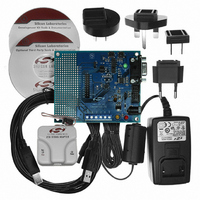
Contents
Evaluation Board, Power Supply, USB Cables, Adapter and Documentation
Processor To Be Evaluated
C8051F33x
Interface Type
RS-232
Operating Supply Voltage
7 V to 15 V
Silicon Manufacturer
Silicon Labs
Core Architecture
8051
Silicon Core Number
C8051F330
Silicon Family Name
C8051F33x
Lead Free Status / RoHS Status
Contains lead / RoHS non-compliant
For Use With/related Products
Silicon Laboratories C8051F330, C8051F331
Lead Free Status / Rohs Status
Lead free / RoHS Compliant
Other names
336-1264


9.
The MCU system controller core is the CIP-51 microcontroller. The CIP-51 is fully compatible with the
MCS-51™ instruction set; standard 803x/805x assemblers and compilers can be used to develop soft-
ware. The MCU family has a superset of all the peripherals included with a standard 8051. Included are
four 16-bit counter/timers (see description in
in
Special Function Register (SFR) address space
tion
directly with the analog and digital subsystems providing a complete data acquisition or control-system
solution in a single integrated circuit.
The CIP-51 Microcontroller core implements the standard 8051 organization and peripherals as well as
additional custom peripherals and functions to extend its capability (see Figure 9.1 for a block diagram).
The CIP-51 includes the following features:
Performance
The CIP-51 employs a pipelined architecture that greatly increases its instruction throughput over the stan-
dard 8051 architecture. In a standard 8051, all instructions except for MUL and DIV take 12 or 24 system
clock cycles to execute, and usually have a maximum system clock of 12 MHz. By contrast, the CIP-51
core executes 70% of its instructions in one or two system clock cycles, with no instructions taking more
than eight system clock cycles.
Section
- Fully Compatible with MCS-51 Instruction
- 25 MIPS Peak Throughput with 25 MHz
- 0 to 25 MHz Clock Frequency
14). The CIP-51 also includes on-chip debug hardware (see description in
CIP-51 Microcontroller
Set
Clock
16), an Enhanced SPI (see description in
RESET
CLOCK
STOP
IDLE
Figure 9.1. CIP-51 Block Diagram
ACCUMULATOR
PROGRAM COUNTER (PC)
CONTROL
PSW
PRGM. ADDRESS REG.
LOGIC
POWER CONTROL
PC INCREMENTER
DATA POINTER
REGISTER
BUFFER
TMP1
PIPELINE
Section
ALU
(Section
Rev. 1.7
TMP2
DATA BUS
DATA BUS
D8
D8
D8
18), an enhanced full-duplex UART (see description
Section
A16
D8
D8
D8
D8
B REGISTER
9.2.6), and 17 Port I/O (see description in
REGISTER
INTERFACE
INTERFACE
INTERRUPT
INTERFACE
- 256 Bytes of Internal RAM
- 17 Port I/O
- Extended Interrupt Handler
- Reset Input
- Power Management Modes
ADDRESS
MEMORY
SRAM
BUS
SFR
C8051F330/1/2/3/4/5
17), 256 bytes of internal RAM, 128 byte
MEM_WRITE_DATA
SFR_WRITE_DATA
MEM_READ_DATA
STACK POINTER
(256 X 8)
SFR_READ_DATA
SRAM
MEM_CONTROL
EMULATION_IRQ
MEM_ADDRESS
SFR_CONTROL
SFR_ADDRESS
SYSTEM_IRQs
Section
20), and interfaces
Sec-
71
Related parts for C8051F330DK
Image
Part Number
Description
Manufacturer
Datasheet
Request
R

Part Number:
Description:
SMD/C°/SINGLE-ENDED OUTPUT SILICON OSCILLATOR
Manufacturer:
Silicon Laboratories Inc
Part Number:
Description:
Manufacturer:
Silicon Laboratories Inc
Datasheet:
Part Number:
Description:
N/A N/A/SI4010 AES KEYFOB DEMO WITH LCD RX
Manufacturer:
Silicon Laboratories Inc
Datasheet:
Part Number:
Description:
N/A N/A/SI4010 SIMPLIFIED KEY FOB DEMO WITH LED RX
Manufacturer:
Silicon Laboratories Inc
Datasheet:
Part Number:
Description:
N/A/-40 TO 85 OC/EZLINK MODULE; F930/4432 HIGH BAND (REV E/B1)
Manufacturer:
Silicon Laboratories Inc
Part Number:
Description:
EZLink Module; F930/4432 Low Band (rev e/B1)
Manufacturer:
Silicon Laboratories Inc
Part Number:
Description:
I°/4460 10 DBM RADIO TEST CARD 434 MHZ
Manufacturer:
Silicon Laboratories Inc
Part Number:
Description:
I°/4461 14 DBM RADIO TEST CARD 868 MHZ
Manufacturer:
Silicon Laboratories Inc
Part Number:
Description:
I°/4463 20 DBM RFSWITCH RADIO TEST CARD 460 MHZ
Manufacturer:
Silicon Laboratories Inc
Part Number:
Description:
I°/4463 20 DBM RADIO TEST CARD 868 MHZ
Manufacturer:
Silicon Laboratories Inc
Part Number:
Description:
I°/4463 27 DBM RADIO TEST CARD 868 MHZ
Manufacturer:
Silicon Laboratories Inc
Part Number:
Description:
I°/4463 SKYWORKS 30 DBM RADIO TEST CARD 915 MHZ
Manufacturer:
Silicon Laboratories Inc
Part Number:
Description:
N/A N/A/-40 TO 85 OC/4463 RFMD 30 DBM RADIO TEST CARD 915 MHZ
Manufacturer:
Silicon Laboratories Inc
Part Number:
Description:
I°/4463 20 DBM RADIO TEST CARD 169 MHZ
Manufacturer:
Silicon Laboratories Inc