C8051F005DK Silicon Laboratories Inc, C8051F005DK Datasheet - Page 77
C8051F005DK
Manufacturer Part Number
C8051F005DK
Description
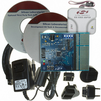
DEV KIT FOR F005/006/007
Manufacturer
Silicon Laboratories Inc
Type
MCUr
Datasheet
1.C8051F005-TB.pdf
(171 pages)
Specifications of C8051F005DK
Contents
Evaluation Board, Power Supply, USB Cables, Adapter and Documentation
Processor To Be Evaluated
C8051F01x
Interface Type
USB
Silicon Manufacturer
Silicon Labs
Core Architecture
8051
Silicon Core Number
C8051F005
Silicon Family Name
C8051F00x
Lead Free Status / RoHS Status
Contains lead / RoHS non-compliant
For Use With/related Products
Silicon Laboratories C8051 F005/006/007
Lead Free Status / Rohs Status
Lead free / RoHS Compliant
Other names
336-1188
Available stocks
Company
Part Number
Manufacturer
Quantity
Price
Company:

Part Number:
C8051F005DK
Manufacturer:
SiliconL
Quantity:
1


10.4.
The CIP-51 includes an extended interrupt system supporting a total of 22 interrupt sources with two priority levels.
The allocation of interrupt sources between on-chip peripherals and external inputs pins varies according to the
specific version of the device. Each interrupt source has one or more associated interrupt-pending flag(s) located in
an SFR. When a peripheral or external source meets a valid interrupt condition, the associated interrupt-pending
flag is set to logic 1.
If interrupts are enabled for the source, an interrupt request is generated when the interrupt-pending flag is set. As
soon as execution of the current instruction is complete, the CPU generates an LCALL to a predetermined address
to begin execution of an interrupt service routine (ISR). Each ISR must end with an RETI instruction, which
returns program execution to the next instruction that would have been executed if the interrupt request had not
occurred. If interrupts are not enabled, the interrupt-pending flag is ignored by the hardware and program execution
continues as normal. (The interrupt-pending flag is set to logic 1 regardless of the interrupt’s enable/disable state.)
Each interrupt source can be individually enabled or disabled through the use of an associated interrupt enable bit in
an SFR (IE-EIE2). However, interrupts must first be globally enabled by setting the EA bit (IE.7) to logic 1 before
the individual interrupt enables are recognized. Setting the EA bit to logic 0 disables all interrupt sources regardless
of the individual interrupt-enable settings.
Some interrupt-pending flags are automatically cleared by the hardware when the CPU vectors to the ISR.
However, most are not cleared by the hardware and must be cleared by software before returning from the ISR. If
an interrupt-pending flag remains set after the CPU completes the return-from-interrupt (RETI) instruction, a new
interrupt request will be generated immediately and the CPU will re-enter the ISR after the completion of the next
instruction.
10.4.1. MCU Interrupt Sources and Vectors
The MCUs allocate 12 interrupt sources to on-chip peripherals. Up to 10 additional external interrupt sources are
available depending on the I/O pin configuration of the device. Software can simulate an interrupt by setting any
interrupt-pending flag to logic 1. If interrupts are enabled for the flag, an interrupt request will be generated and the
CPU will vector to the ISR address associated with the interrupt-pending flag. MCU interrupt sources, associated
vector addresses, priority order and control bits are summarized in Table 10.4. Refer to the datasheet section
associated with a particular on-chip peripheral for information regarding valid interrupt conditions for the peripheral
and the behavior of its interrupt-pending flag(s).
10.4.2. External Interrupts
Two of the external interrupt sources (/INT0 and /INT1) are configurable as active-low level-sensitive or active-low
edge-sensitive inputs depending on the setting of IT0 (TCON.0) and IT1 (TCON.2).
(TCON.3) serve as the interrupt-pending flag for the /INT0 and /INT1 external interrupts, respectively. If an /INT0
or /INT1 external interrupt is configured as edge-sensitive, the corresponding interrupt-pending flag is automatically
cleared by the hardware when the CPU vectors to the ISR. When configured as level sensitive, the interrupt-
pending flag follows the state of the external interrupt’s input pin. The external interrupt source must hold the input
active until the interrupt request is recognized. It must then deactivate the interrupt request before execution of the
ISR completes or another interrupt request will be generated.
The remaining four external interrupts (External Interrupts 4-7) are active-low, edge-sensitive inputs. The interrupt-
pending flags for these interrupts are in the Port 1 Interrupt Flag Register shown in Figure 15.10.
77
C8051F000/1/2/5/6/7
C8051F010/1/2/5/6/7
INTERRUPT HANDLER
Rev. 1.7
IE0 (TCON.1) and IE1
Related parts for C8051F005DK
Image
Part Number
Description
Manufacturer
Datasheet
Request
R

Part Number:
Description:
SMD/C°/SINGLE-ENDED OUTPUT SILICON OSCILLATOR
Manufacturer:
Silicon Laboratories Inc
Part Number:
Description:
Manufacturer:
Silicon Laboratories Inc
Datasheet:
Part Number:
Description:
N/A N/A/SI4010 AES KEYFOB DEMO WITH LCD RX
Manufacturer:
Silicon Laboratories Inc
Datasheet:
Part Number:
Description:
N/A N/A/SI4010 SIMPLIFIED KEY FOB DEMO WITH LED RX
Manufacturer:
Silicon Laboratories Inc
Datasheet:
Part Number:
Description:
N/A/-40 TO 85 OC/EZLINK MODULE; F930/4432 HIGH BAND (REV E/B1)
Manufacturer:
Silicon Laboratories Inc
Part Number:
Description:
EZLink Module; F930/4432 Low Band (rev e/B1)
Manufacturer:
Silicon Laboratories Inc
Part Number:
Description:
I°/4460 10 DBM RADIO TEST CARD 434 MHZ
Manufacturer:
Silicon Laboratories Inc
Part Number:
Description:
I°/4461 14 DBM RADIO TEST CARD 868 MHZ
Manufacturer:
Silicon Laboratories Inc
Part Number:
Description:
I°/4463 20 DBM RFSWITCH RADIO TEST CARD 460 MHZ
Manufacturer:
Silicon Laboratories Inc
Part Number:
Description:
I°/4463 20 DBM RADIO TEST CARD 868 MHZ
Manufacturer:
Silicon Laboratories Inc
Part Number:
Description:
I°/4463 27 DBM RADIO TEST CARD 868 MHZ
Manufacturer:
Silicon Laboratories Inc
Part Number:
Description:
I°/4463 SKYWORKS 30 DBM RADIO TEST CARD 915 MHZ
Manufacturer:
Silicon Laboratories Inc
Part Number:
Description:
N/A N/A/-40 TO 85 OC/4463 RFMD 30 DBM RADIO TEST CARD 915 MHZ
Manufacturer:
Silicon Laboratories Inc
Part Number:
Description:
I°/4463 20 DBM RADIO TEST CARD 169 MHZ
Manufacturer:
Silicon Laboratories Inc