DEMO9S08JS16 Freescale Semiconductor, DEMO9S08JS16 Datasheet
DEMO9S08JS16
Specifications of DEMO9S08JS16


Related parts for DEMO9S08JS16

DEMO9S08JS16 Summary of contents
Page 1
...
Page 2
Purchase Agreement P&E Microcomputer Systems, Inc. reserves the right to make changes without further notice to any products herein to improve reliability, function, or design. P&E Microcomputer Systems, Inc. does not assume any liability arising out of the application or ...
Page 3
... On-Board Logic Analyzer ............................................................................... 4 2.3 On-Board Virtual USB Port............................................................................. 4 2.4 DEMO9S08JS16 Daughter Card Features .................................................... 5 2.5 DEMOJM Board Jumper/Connector Quick Reference................................... 5 2.6 Signal Mapping of DC9S08JS16 to MCU_PORT........................................... 8 3 GETTING STARTED WITH THE DEMO9S08JS16 ....................................... 9 4 SYSTEM SETUP ............................................................................................ 9 4.1 Overview ........................................................................................................ 9 4.2 Operating System Requirements ................................................................ 10 4.3 Software Setup............................................................................................. 10 4.4 Quick Startup ...
Page 4
... Buzzer...........................................................................................................35 8.9 IIC Pull-up .....................................................................................................36 8.10 Analog Input Potentiometer ..........................................................................36 8.11 Optional Jumpers For Various VDD And VSS ..............................................36 9 DEMO9S08JS16 CODE DEVELOPMENT SOFTWARE.............................. 37 9.1 Using CodeWarrior With The DEMO9S08JS16............................................37 9.2 P&E Software Tools for HCS08 Microcontrollers..........................................37 10 TRANSITIONING TO YOUR OWN TARGET ............................................... 38 10.1 Hardware Solutions At A Glance ..................................................................38 10.2 Working With P& ...
Page 5
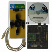
... INTRODUCTION 1.1 Overview The DEMO9S08JS16 is a low cost development system supporting Freescale MC9S08JS16 microcontrollers. It consists of a DEMOJM Base Board and a DC9S08JS16 Daughter Card. P&E’s Embedded Multilink circuitry on the DEMOJM board allows the processor connected to the DEMOJM to be debugged and programmed via USB from a PC. In addition, the demo board can be powered using the USB bus ...
Page 6
... HARDWARE FEATURES The DEMO9S08JS16 is a demonstration and development system for Freescale’s MC9S08JS16 microcontrollers. Application development is quick and easy using P&E’s Embedded Multilink circuitry and the included software tools and examples. An optional BDM port is provided to allow the use of an external BDM interface such as P& ...
Page 7
... Note: The DEMOJM board power connector is incorrectly labelled as 6-12VDC. The maximum voltage is 8VDC. DEMO9S08JS16 User Manual Power Input from Embedded Multilink to LDO regulator Power Input from DC Power Jack to LDO regulator Power Input from Mini-AB connector Power Input from MCU_PORT connector ...
Page 8
... The DEMOJM board has a built-in virtual serial port which may be connected to the JM processor’s SCI RXD/TXD. This allows certain PC applications to be able to connect in a serial fashion to the microcontroller without the actual use of serial port hardware. The Terminal Window Utility, included in the P&E Embedded Multilink Toolkit 4 DEMO9S08JS16 User Manual ...
Page 9
... DVD-ROM generic serial port utility which works with the DEMOJM virtual serial port or actual serial port hardware. 2.4 DEMO9S08JS16 Daughter Card Features • Four (4) bottom-mounted asymmetrically positioned 8x2 female connectors to mate with the DEMOJM Base Board • A top-mounted MC9S08JS16CFK chip • ...
Page 10
... J10 OFF J11 1&2 J12 1&2 J13 ALL OFF J14 ALL OFF J15 OFF J16 OFF 1&2, 3&4, 5&6, 7&8, 9&10, J17 11&12, 13&14, 15&16 J18 2&3 J19 2&3 J20 2&3 J21 ALL OFF J24 1&2 DEMO9S08JS16 User Manual ...
Page 11
... DEMO9S08JS16 User Manual Default Jumper Settings J27 1&2, 3&4, 5&6, 7&8 J28 1&2, 3&4 J29 1&2, 3&4 J30 1&2 J31 ALL OFF J32 ALL OFF J33 1&2 7 ...
Page 12
... Signal Mapping of DC9S08JS16 to MCU_PORT PIN NUMBER Signal Mapping SIGNAL NUMBER VDD VSS PTA7/KBIP7/TXD PTA6/KBIP6/RXD PTB3/BLMS PTA1/KBIP1/MISO PTA0/KBIP0/ TPMCH0 PTA5/KBIP5/ TPMCH1 PTA2/KBIP2/MOSI PTA1/KBIP1/MISO PTA3/KBIP3/SPSCK PTA4/KBIP4/ VREFH VREFL PIN SIGNAL 2 PTB0/IRQ/TCLK 4 PTB1/~RESET 6 PTB2/BKGD/MS 8 VUSB33 10 PTB0/IRQ/TCLK 12 PTB1/RESET 14 PTB2/BKGD/MS 16 PTB3/BLMS 18 PTB4/XTAL 20 PTB5/EXTAL PTA6/KBIP6/RXD 32 PTA7/KBIP7/TXD DEMO9S08JS16 User Manual ...
Page 13
... The DEMO9S08JS16 is a low-cost board targeting quick microcontroller evaluation. . The board includes a power terminal to measure the ultra-low power consumption of Freescale’s JM devices. Please refer to the DEMO9S08JS16 Quick Start Guide and Labs for instructions on how to install software, connect the DEMO9S08JS16 to your PC, and run quick demonstrations. 4 SYSTEM SETUP 4 ...
Page 14
... To install the CodeWarrior Development Studio, follow the instructions on the DVD-ROM. 4.3.2 Installing P&E Resources Use the DEMO9S08JS16 Resources in the DVD-ROM to access and install P&E resources for the DEMO9S08JS16. These materials are not required for operation. The DEMO9S08JS16 Resources in the Getting Started DVD-ROM contains the following support materials: • ...
Page 15
... Links to Freescale documentation, P&E Discussion Forums, and DEMO9S08JS16 FAQs. 4.4 Quick Startup Only a few steps are required to get the DEMO9S08JS16 up and running. Please reference the Quick Start Guide. 4.5 Hardware Setup 4.5.1 First-Time Connection The DEMO9S08JS16 may be connected through a USB port. ...
Page 16
... Figure 4-1: Found New Hardware Wizard Dialog ( Select the “Install the software automatically (Recommended)” option and click the “Next” button. 6. Windows will install the driver files to your system. At the end of the installation, the following dialog box will appear: 12 DEMO9S08JS16 User Manual ...
Page 17
... Click the “Finish” button to exit the current “Found New Hardware Wizard”. 7. Depending on the operating system, you may see the “Found New Hardware Wizard” dialog again to assist you with software installation for “PEMicro USB Serial Port (i1).” On Windows XP (SP2), the follow- ing dialog will appear: DEMO9S08JS16 User Manual 13 ...
Page 18
... Figure 4-3: Found New Hardware Wizard Dialog ( Select the “Install the software automatically (Recommended)” option and click the “Next” button. 8. Windows will install the driver files to your system. At the end of the installation, the following dialog box will appear: 14 DEMO9S08JS16 User Manual ...
Page 19
... Below are some of the featured operating modes of the DEMO9S08JS16. 5.2 Debug Mode A host communicates with the DEMO9S08JS16 through the Embedded Multilink circuitry. Either the CodeWarrior Development Studio or P&E’s HCS08 software tools will work with the DEMO9S08JS16. Please refer to DEMO9S08JS16 User Manual 15 ...
Page 20
... Section 9 - DEMO9S08JS16 CODE DEVELOPMENT SOFTWARE for more information. 5.3 Run Mode The DEMO9S08JS16’s rich component list empowers it to perform a variety of tasks. Once an application is developed, debugged, and programmed properly into the JM internal flash memory, it can run with or without connecting to a host. ...
Page 21
... MCU, the IN0 channel will show the PWM output on pin PTE2, whose duty cycle is controlled by the potentiometer (W1). The IN1 channel shows the PWM output on channel PTE3. This PC-based application is included on the DVD-ROM that accompanies the DEMO9S08JS16, and may also be found at: http://www.pemicro.com/fixedlinks/demotoolkit.cfm. 6.2 Terminal Application This PC-based application acts as a standard serial port terminal application on the PC ...
Page 22
... USB or DB9 serial cable into the evaluation board and click on the Open Serial Port button. This PC-based application is included on the DVD-ROM that accompanies the DEMO9S08JS16, and may also be found at: http://www.pemicro.com/fixedlinks/demotoolkit.cfm. 6.3 DEMO9S08JS16 Unsecure Application This application allows secure HCS08 microcontrollers to be unsecured ...
Page 23
... Port text box. Please select HCS08 or CFV1 from the Select Architecture drop down menu and press the Perform Unsecure button. The application will finish unsecuring and erasing the device shortly thereafter. This PC-based application is included on the DVD-ROM that accompanies the DEMO9S08JS16, and may also be found at: http://www.pemicro.com/fixedlinks/demotoolkit.cfm. 6.4 Accelerometer Demo Application This PC-based application will graph serial data output from the microcontroller-based serial accelerometer application ...
Page 24
... Data Snapshot window will display the accelerometer and potentiometer data levels in the form of a bar graph. The graphing of data can be paused and the scale of the X and Y axes can be changed via a tool bar located in the top right corner of the Accelerometer Demo Application. 20 DEMO9S08JS16 User Manual ...
Page 25
... This PC-based application is included on the DVD-ROM that accompanies the DEMO9S08JS16, and may also be found at: http://www.pemicro.com/fixedlinks/demotoolkit.cfm. 6.5 Serial Grapher Application This PC-based application is a more generalized version of the accelerometer demo application. It may be used with the microcontroller-based serial accelerometer application or custom microcontroller code which transmits data in the correct format. The serial graphing utility allows incoming data on the PC serial port (or one of P& ...
Page 26
... As can be seen in Data Format, each incoming data command affecting the graphing component must have new data for all four waveforms. An example graph is shown here: 22 Figure 6-5: Serial Grapher Bar Graph DEMO9S08JS16 User Manual ...
Page 27
... CR (carriage return) and LF (line feed). The accepted commands are: WnnZnnYnnXnn The nn values are 00-FF and correspond in order to the data displayed on the following graph lines AnnBnnCnnDnn The nn values are 00-FF and correspond in order to the data displayed on the following bar graphs lines DEMO9S08JS16 User Manual 23 ...
Page 28
... Embedded Multilink design). Jumper J4 controls this connection. P&E has two PC-based P&E Embedded Multilink Toolkit applications which allow the serial port data generated by this application to be graphed. These are documented in Section 6.4 - Accelerometer Demo Application and Section 6.5 - Serial Grapher Application. 24 DEMO9S08JS16 User Manual ...
Page 29
... The DEMOJM board has a built-in virtual serial port which may be connected to the JM processor’s SCI RXD1/TXD1. This allows certain PC applications to be able to connect in a serial fashion to the microcontroller without the actual use of serial port hardware. It can be enabled or disabled by installing or removing the jumpers of J4. DEMO9S08JS16 User Manual 25 ...
Page 30
... A jumper across 1 & 2 selects silent mode. This selection also allows the microcontroller to control the operation mode via PTD6. A jumper across 2 & 3 selects high speed mode. This is the default setting. Figure 8-4: Can Operation Mode Selection (J6) 26 Figure 8-2: Virtual Serial Port Header (J4) Figure 8-3: CAN Signals (J5) DEMO9S08JS16 User Manual ...
Page 31
... A jumper across 1 & 2 disables USB host power generation. This selection also pulls up PTB3 and allows the microcontroller to use PTB3 to control the USB host power generation. Pay extra attention to this signal shared DEMO9S08JS16 User Manual Figure 8-5: CAN Transmit Enable (J7) Figure 8-6: CAN Port Enable CAN_EN ...
Page 32
... A jumper across 1 & 2 indicates that the Mini-USB will be powered from the bus. This is the default setting. A jumper across 2 & 3 indicates that the Mini-USB will provide power as a host. Figure 8-8: Mini-USB Bus power selection (J12) 8.4.4 J13 – Determines whether USBDN is pulled down directly or controlled by 28 DEMO9S08JS16 User Manual ...
Page 33
... A jumper across 2 & 3 indicates that the USB_DN_DOWN signal controls the pull down of USBDN signal. This is the default setting. 8.4.5 J14 – Determines whether USBDP is pulled down directly or controlled by USB_DP_DOWN signal A jumper across 1 & 2 pulls down USBDP directly. DEMO9S08JS16 User Manual Figure 8-9: USBDN Setting (J13) 29 ...
Page 34
... USB_PULLUP signal By default this jumper is not installed. In summary, use the following jumper settings for Mini-USB device mode operation: J11: 1&2 J12: 1&2 J13: 2&3 30 Figure 8-10: USBDP Settings (J14) Figure 8-11: USB_ID signal connect (J15) Figure 8-12: USB_PULLUP (J16) DEMO9S08JS16 User Manual ...
Page 35
... Enables all LED outputs. This is the default setting. Figure 8-13: LED Display Enable Header LED_ENABLE (J17) 8.6 Input and Reset Switches The DEMOJM has 4 switches that are connected to signals PTG0, PTG1, PTG2, and PTG3 respectively, and are enabled or disabled by the 4 corresponding jumpers KEY_ENABLE (J27). DEMO9S08JS16 User Manual 31 ...
Page 36
... J27 - Light Touch Switch Enable Jumper KEY_ENABLE Enables the corresponding switch. Each jumper may be individually installed or removed. By default, all jumpers are installed to enable all the switches. Figure 8-15: Jumper Settings for Light Touch Switches KEY_ENABLE (J27) 32 INPUT_EN (J28) DEMO9S08JS16 User Manual ...
Page 37
... Accelerometer Jumper Settings The DEMOJM integrates a 3-axis accelerometer. Its enable/disable, sensitivity levels, and output signal connections are all jumper-setable. Jumpers J18, J19, J20 and J21 are associated with the accelerometer. DEMO9S08JS16 User Manual Accelerometer G-Select Pin Descriptions G-SEL2 G-SEL1 g-Range ...
Page 38
... Figure 8-17: Accelerometer g-Select1 Jumper settings (J18) 8.7.2 J19 - Accelerometer g-Select2 Jumper G-SEL2 Selects g-Select2 to be logic low. This is the default setting. Selects g-Select2 to be logic high. A user may control PTD7 in firmware to set g-Select2 Figure 8-18: Accelerometer g-Select2 Jumper settings (J19) 34 DEMO9S08JS16 User Manual ...
Page 39
... PTB3, and PTD0. PTB3 and PTD0 share the same X-axis signal. By default, the X-axis signal is connected to PTB3. Figure 8-20: Accelerometer Signal Output ACC_EN (J21) 8.8 Buzzer The DEMOJM integrates a Piezo Transducer whose resonant frequency is 4.0 KHz. Jumper J30 connects to PTF4 to control this buzzer. DEMO9S08JS16 User Manual 35 ...
Page 40
... Figure 8-23: Potentiometer Output Selection Jumpers POT_EN (J32) 8.11 Optional Jumpers For Various VDD And VSS The DEMOJM provides 5 jumpers, J22 through J26, for different VDD and VSS connections on the bottom of the board. By default, they are not 36 DEMO9S08JS16 User Manual ...
Page 41
... The DEMOJM board includes P&E’s Embedded Multilink circuitry external hardware BDM tool is needed to debug and program the DEMO9S08JS16. A user only needs to connect the DEMOJM board to their PC to start developing code for it. The DEMO9S08JS16 package comes with a special edition of Freescale’s CodeWarrior studio. In addition, P& ...
Page 42
... TRANSITIONING TO YOUR OWN TARGET Once you have finished working with the DEMO9S08JS16 and are ready to build your own target, you will need a hardware tool to allow you to develop using your own board. P&E’s USB Multilink and P&E’s Cyclone PRO offer two effective solutions, depending on your needs. Both work with Freescale’ ...
Page 43
... By using the USB Multilink Interface, the user can take advantage of the background debug mode to halt normal processor execution and use control the processor. The user can then directly control the target’s DEMO9S08JS16 User Manual PC-Controlled and User-Controlled Stand-Alone Operation Interactive Programming via Host PC ...
Page 44
... PC. Once loaded with data can be disconnected and operated manually in a stand-alone mode via the LCD menu and control buttons. The Cyclone PRO has over 3Mbytes of non-volatile memory, which 40 Figure 10-2: P&E’s Cyclone PRO DEMO9S08JS16 User Manual ...
Page 45
... The DEMOJM board shows up in Window’s device manager as a “P&E Multilink,” since it contains P&E’s Embedded Multilink circuitry. If you unplug and then plug in the device, Windows will automatically disable it even if you have installed the drivers. To DEMO9S08JS16 User Manual 41 ...
Page 46
... PC are high-power (self-powered) ports. 11.2 CodeWarrior Installation Fails (WinDriver Error) Q: When I try to install the Codewarrior or P&E software, installation fails with this message: “There are currently 2 open applications using WinDriver. Please close all applications and press Retry. To reload WinDriver, press 42 DEMO9S08JS16 User Manual ...
Page 47
... At the bottom of the System Devices list, you should see a WinDriver item. 6. Right-click on WinDriver and select Enable from the drop-down menu. Reboot your PC after the installation finishes. If you are unable to disable the WinDriver system driver in the above fashion, you can delete the file c:\windows\system32\windrvr6.sys and then reboot DEMO9S08JS16 User Manual 43 ...
Page 48
... You should then re-run the installer and complete the procedure. Reboot your machine after the installation has finished. 44 DEMO9S08JS16 User Manual ...
Page 49
...