C8051F410DK Silicon Laboratories Inc, C8051F410DK Datasheet
C8051F410DK
Manufacturer Part Number
C8051F410DK
Description
KIT DEV FOR C8051F41X
Manufacturer
Silicon Laboratories Inc
Type
MCUr
Specifications of C8051F410DK
Contents
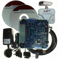
Evaluation Board, Power Supply, USB Cables, Adapter and Documentation
Processor To Be Evaluated
C8051F41x
Interface Type
USB
Silicon Manufacturer
Silicon Labs
Core Architecture
8051
Silicon Core Number
C8051F410
Silicon Family Name
C8051F41x
Lead Free Status / RoHS Status
Contains lead / RoHS non-compliant
For Use With/related Products
Silicon Laboratories C8051F41x
Lead Free Status / Rohs Status
Lead free / RoHS Compliant
Other names
336-1314
Available stocks
Company
Part Number
Manufacturer
Quantity
Price
Company:

Part Number:
C8051F410DK
Manufacturer:
Silicon Labs
Quantity:
135


January 7, 2008
Errata Status Summary
Impact Definition: Each erratum is marked with an impact, as defined below:
Errata Details
1. Description: The XTLVLD bit in the OSCXCN register may not properly indicate when an external crystal
Errata
•
•
•
oscillator is running and stable. The XTLVLD bit may read as 0, even if the crystal is properly oscillating.
Impact: The recommended procedure in the datasheet for using an external oscillator as the system clock
includes a step to poll the XTLVLD bit. Since the XTLVLD bit may not correctly indicate the status of the
external crystal, this procedure is no longer valid.
Workaround: The firmware can determine if the external oscillator is running by using the external oscillator
as the clock source for the PCA or one of the four Timers. Once enabled, if the PCA or Timer counter counts
the expected number of cycles over a fixed period of time, the firmware can safely switch to the external
oscillator as the system clock. Using the external oscillator as the clock source for a PCA or Timer does not
require switching to the crystal oscillator as the main system clock. Once the crystal oscillator is selected as
the system clock, the PCA or Timer no longer needs to be used for this purpose.
The updated procedure for using a crystal oscillator as the system clock is provided below. Contact
mcuapps@silabs.com
Step 1
Step 2
Step 3
Step 4
Step 5
Step 6
Step 7
Step 8
Step 9
#
1
2
400 West Cesar Chavez, Austin, TX 78701 (512) 416-8500 FAX (512) 416-9669 www.silabs.com
Minor—Workaround exists.
Major—Errata that do not conform to the data sheet or standard.
Information—The device behavior is not ideal but acceptable. Typically, the data sheet will be
changed to match the device behavior.
XTLVLD is incorrect
Port Pin Overvoltage
Force the XTAL1 and XTAL2 pins low by writing 0s to the port latch.
Configure XTAL1 and XTAL2 as analog inputs.
Release the crystal pins by writing 1s to the port latch.
Enable the external oscillator.
Wait at least 1 ms.
Configure the PCA or a Timer to use the external oscillator as the clock source.
Monitor the PCA or Timer over a fixed period of system clock cycles to ensure the external
oscillator is oscillating at the correct speed.
Enable the Missing Clock Detector as a Reset Source.
Switch the system clock to the external oscillator.
Title
for example code that implements this procedure.
C8051F41x Revisions A-F Errata
C8051F41xERA-F010708
Impact
Minor
Minor
Affected Revisions
Revision E only
Revisions A-F
Status
Fixed in Revision F
Fixed Revision
Not Fixed
Related parts for C8051F410DK
Image
Part Number
Description
Manufacturer
Datasheet
Request
R

Part Number:
Description:
SMD/C�/SINGLE-ENDED OUTPUT SILICON OSCILLATOR
Manufacturer:
Silicon Laboratories Inc
Part Number:
Description:
Manufacturer:
Silicon Laboratories Inc
Datasheet:
Part Number:
Description:
N/A N/A/SI4010 AES KEYFOB DEMO WITH LCD RX
Manufacturer:
Silicon Laboratories Inc
Datasheet:
Part Number:
Description:
N/A N/A/SI4010 SIMPLIFIED KEY FOB DEMO WITH LED RX
Manufacturer:
Silicon Laboratories Inc
Datasheet:
Part Number:
Description:
N/A/-40 TO 85 OC/EZLINK MODULE; F930/4432 HIGH BAND (REV E/B1)
Manufacturer:
Silicon Laboratories Inc
Part Number:
Description:
EZLink Module; F930/4432 Low Band (rev e/B1)
Manufacturer:
Silicon Laboratories Inc
Part Number:
Description:
I�/4460 10 DBM RADIO TEST CARD 434 MHZ
Manufacturer:
Silicon Laboratories Inc
Part Number:
Description:
I�/4461 14 DBM RADIO TEST CARD 868 MHZ
Manufacturer:
Silicon Laboratories Inc
Part Number:
Description:
I�/4463 20 DBM RFSWITCH RADIO TEST CARD 460 MHZ
Manufacturer:
Silicon Laboratories Inc
Part Number:
Description:
I�/4463 20 DBM RADIO TEST CARD 868 MHZ
Manufacturer:
Silicon Laboratories Inc
Part Number:
Description:
I�/4463 27 DBM RADIO TEST CARD 868 MHZ
Manufacturer:
Silicon Laboratories Inc
Part Number:
Description:
I�/4463 SKYWORKS 30 DBM RADIO TEST CARD 915 MHZ
Manufacturer:
Silicon Laboratories Inc
Part Number:
Description:
N/A N/A/-40 TO 85 OC/4463 RFMD 30 DBM RADIO TEST CARD 915 MHZ
Manufacturer:
Silicon Laboratories Inc
Part Number:
Description:
I�/4463 20 DBM RADIO TEST CARD 169 MHZ
Manufacturer:
Silicon Laboratories Inc
C8051F410DK Summary of contents
Page 1
January 7, 2008 C8051F41x Revisions A-F Errata Errata Status Summary Errata Title # 1 XTLVLD is incorrect 2 Port Pin Overvoltage Impact Definition: Each erratum is marked with an impact, as defined below: • Minor—Workaround exists. • Major—Errata that do ...
Page 2
Description: Port pins that are programmed for push-pull output mode and a logic-high state (‘1’ written to the port pin latch) may become forced to a logic-low state if exposed to an overvoltage condition that exceeds the specified limits ...