C8051F410DK Silicon Laboratories Inc, C8051F410DK Datasheet - Page 152
C8051F410DK
Manufacturer Part Number
C8051F410DK
Description
KIT DEV FOR C8051F41X
Manufacturer
Silicon Laboratories Inc
Type
MCUr
Specifications of C8051F410DK
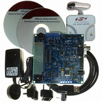
Contents
Evaluation Board, Power Supply, USB Cables, Adapter and Documentation
Processor To Be Evaluated
C8051F41x
Interface Type
USB
Silicon Manufacturer
Silicon Labs
Core Architecture
8051
Silicon Core Number
C8051F410
Silicon Family Name
C8051F41x
Lead Free Status / RoHS Status
Contains lead / RoHS non-compliant
For Use With/related Products
Silicon Laboratories C8051F41x
Lead Free Status / Rohs Status
Lead free / RoHS Compliant
Other names
336-1314
Available stocks
Company
Part Number
Manufacturer
Quantity
Price
Company:

Part Number:
C8051F410DK
Manufacturer:
Silicon Labs
Quantity:
135


C8051F410/1/2/3
The output driver characteristics of the I/O pins are defined using the Port Output Mode registers (PnMD-
OUT). Each Port Output driver can be configured as either open drain or push-pull. This selection is
required even for the digital resources selected in the XBRn registers, and is not automatic. The only
exception to this is the SMBus (SDA, SCL) pins, which are configured as open-drain regardless of the
PnMDOUT settings. When the WEAKPUD bit in XBR1 is ‘0’, a weak pullup is enabled for all Port I/O con-
figured as open-drain. WEAKPUD does not affect the push-pull Port I/O. Furthermore, the weak pullup is
turned off on an output that is driving a ‘0’ and for pins configured for analog input mode to avoid unneces-
sary power dissipation.
Registers XBR0 and XBR1 must be loaded with the appropriate values to select the digital I/O functions
required by the design. Setting the XBARE bit in XBR1 to ‘1’ enables the Crossbar. Until the Crossbar is
enabled, the external pins remain as standard Port I/O (in input mode), regardless of the XBRn Register
settings. For given XBRn Register settings, one can determine the I/O pin-out using the Priority Decode
Table.
The Crossbar must be enabled to use Port pins as standard Port I/O in output mode. Port output drivers
are disabled while the Crossbar is disabled.
152
V
Cell
I/O
V
IO
DD
Figure 18.5. Port 0 Input Overdrive Current Range
P0.x
pin
I
Vtest
+
-
V
test
High-Impedance Mode
P0ODEN.x = 0
P0ODEN.x = 1
Rev. 1.1
Normal Mode
I
I
Vtest
Vtest
(µA)
(µA)
-150
-10
-10
10
0
0
V
IO
V
-0.2
IO
V
V
IO
IO
+0.7
+0.2
V
V
test
test
(V)
(V)
Related parts for C8051F410DK
Image
Part Number
Description
Manufacturer
Datasheet
Request
R

Part Number:
Description:
SMD/C°/SINGLE-ENDED OUTPUT SILICON OSCILLATOR
Manufacturer:
Silicon Laboratories Inc
Part Number:
Description:
Manufacturer:
Silicon Laboratories Inc
Datasheet:
Part Number:
Description:
N/A N/A/SI4010 AES KEYFOB DEMO WITH LCD RX
Manufacturer:
Silicon Laboratories Inc
Datasheet:
Part Number:
Description:
N/A N/A/SI4010 SIMPLIFIED KEY FOB DEMO WITH LED RX
Manufacturer:
Silicon Laboratories Inc
Datasheet:
Part Number:
Description:
N/A/-40 TO 85 OC/EZLINK MODULE; F930/4432 HIGH BAND (REV E/B1)
Manufacturer:
Silicon Laboratories Inc
Part Number:
Description:
EZLink Module; F930/4432 Low Band (rev e/B1)
Manufacturer:
Silicon Laboratories Inc
Part Number:
Description:
I°/4460 10 DBM RADIO TEST CARD 434 MHZ
Manufacturer:
Silicon Laboratories Inc
Part Number:
Description:
I°/4461 14 DBM RADIO TEST CARD 868 MHZ
Manufacturer:
Silicon Laboratories Inc
Part Number:
Description:
I°/4463 20 DBM RFSWITCH RADIO TEST CARD 460 MHZ
Manufacturer:
Silicon Laboratories Inc
Part Number:
Description:
I°/4463 20 DBM RADIO TEST CARD 868 MHZ
Manufacturer:
Silicon Laboratories Inc
Part Number:
Description:
I°/4463 27 DBM RADIO TEST CARD 868 MHZ
Manufacturer:
Silicon Laboratories Inc
Part Number:
Description:
I°/4463 SKYWORKS 30 DBM RADIO TEST CARD 915 MHZ
Manufacturer:
Silicon Laboratories Inc
Part Number:
Description:
N/A N/A/-40 TO 85 OC/4463 RFMD 30 DBM RADIO TEST CARD 915 MHZ
Manufacturer:
Silicon Laboratories Inc
Part Number:
Description:
I°/4463 20 DBM RADIO TEST CARD 169 MHZ
Manufacturer:
Silicon Laboratories Inc