C8051F410DK Silicon Laboratories Inc, C8051F410DK Datasheet - Page 25
C8051F410DK
Manufacturer Part Number
C8051F410DK
Description
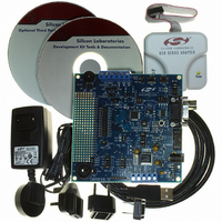
KIT DEV FOR C8051F41X
Manufacturer
Silicon Laboratories Inc
Type
MCUr
Specifications of C8051F410DK
Contents
Evaluation Board, Power Supply, USB Cables, Adapter and Documentation
Processor To Be Evaluated
C8051F41x
Interface Type
USB
Silicon Manufacturer
Silicon Labs
Core Architecture
8051
Silicon Core Number
C8051F410
Silicon Family Name
C8051F41x
Lead Free Status / RoHS Status
Contains lead / RoHS non-compliant
For Use With/related Products
Silicon Laboratories C8051F41x
Lead Free Status / Rohs Status
Lead free / RoHS Compliant
Other names
336-1314
Available stocks
Company
Part Number
Manufacturer
Quantity
Price
Company:

Part Number:
C8051F410DK
Manufacturer:
Silicon Labs
Quantity:
135


1.1.
1.1.1. Fully 8051 Compatible Instruction Set
The C8051F41x devices use Silicon Laboratories’ proprietary CIP-51 microcontroller core. The CIP-51 is
fully compatible with the MCS-51™ instruction set. Standard 803x/805x assemblers and compilers can be
used to develop software. The C8051F41x family has a superset of all the peripherals included with a stan-
dard 8052.
1.1.2. Improved Throughput
The CIP-51 employs a pipelined architecture that greatly increases its instruction throughput over the stan-
dard 8051 architecture. In a standard 8051, all instructions except for MUL and DIV take 12 or 24 system
clock cycles to execute, and usually have a maximum system clock of 12-to-24 MHz. By contrast, the CIP-
51 core executes 70% of its instructions in one or two system clock cycles, with no instructions taking more
than eight system clock cycles.
With the CIP-51's system clock running at 50 MHz, it has a peak throughput of 50 MIPS. The CIP-51 has a
total of 109 instructions. The table below shows the total number of instructions that require each execution
time.
1.1.3. Additional Features
The C8051F41x SoC family includes several key enhancements to the CIP-51 core and peripherals to
improve performance and ease of use in end applications.
An extended interrupt handler allows the numerous analog and digital peripherals to operate indepen-
dently of the controller core and interrupt the controller only when necessary. By requiring less intervention
from the microcontroller core, an interrupt-driven system is more efficient and allows for easier implemen-
tation of multi-tasking, real-time systems.
Eight reset sources are available: power-on reset circuitry (POR), an on-chip V
Timer, a Missing Clock Detector, a voltage level detection from Comparator0, a smaRTClock alarm or
missing smaRTClock clock detector reset, a forced software reset, an external reset pin, and an illegal
Flash access protection circuit. Each reset source except for the POR, Reset Input Pin, or Flash error may
be disabled by the user in software. The WDT may be permanently enabled in software after a power-on
reset during MCU initialization.
The internal oscillator is factory calibrated to 24.5 MHz ±2%. An external oscillator drive circuit is also
included, allowing an external crystal, ceramic resonator, capacitor, RC, or CMOS clock source to generate
the system clock. A clock multiplier allows for operation at up to 50 MHz. The dedicated smaRTClock oscil-
lator can be extremely useful in low power applications, allowing the system to maintain accurate time
while the MCU is not powered, or its internal oscillator is suspended. The MCU can be reset or have its
oscillator awakened using the smaRTClock alarm function.
Number of Instructions
Clocks to Execute
CIP-51™ Microcontroller
26
1
50
2
2/4
5
Rev. 1.1
10
3
3/5
7
4
5
C8051F410/1/2/3
5
2
DD
4/6
monitor, a Watchdog
1
6
2
8
1
25
Related parts for C8051F410DK
Image
Part Number
Description
Manufacturer
Datasheet
Request
R

Part Number:
Description:
SMD/C°/SINGLE-ENDED OUTPUT SILICON OSCILLATOR
Manufacturer:
Silicon Laboratories Inc
Part Number:
Description:
Manufacturer:
Silicon Laboratories Inc
Datasheet:
Part Number:
Description:
N/A N/A/SI4010 AES KEYFOB DEMO WITH LCD RX
Manufacturer:
Silicon Laboratories Inc
Datasheet:
Part Number:
Description:
N/A N/A/SI4010 SIMPLIFIED KEY FOB DEMO WITH LED RX
Manufacturer:
Silicon Laboratories Inc
Datasheet:
Part Number:
Description:
N/A/-40 TO 85 OC/EZLINK MODULE; F930/4432 HIGH BAND (REV E/B1)
Manufacturer:
Silicon Laboratories Inc
Part Number:
Description:
EZLink Module; F930/4432 Low Band (rev e/B1)
Manufacturer:
Silicon Laboratories Inc
Part Number:
Description:
I°/4460 10 DBM RADIO TEST CARD 434 MHZ
Manufacturer:
Silicon Laboratories Inc
Part Number:
Description:
I°/4461 14 DBM RADIO TEST CARD 868 MHZ
Manufacturer:
Silicon Laboratories Inc
Part Number:
Description:
I°/4463 20 DBM RFSWITCH RADIO TEST CARD 460 MHZ
Manufacturer:
Silicon Laboratories Inc
Part Number:
Description:
I°/4463 20 DBM RADIO TEST CARD 868 MHZ
Manufacturer:
Silicon Laboratories Inc
Part Number:
Description:
I°/4463 27 DBM RADIO TEST CARD 868 MHZ
Manufacturer:
Silicon Laboratories Inc
Part Number:
Description:
I°/4463 SKYWORKS 30 DBM RADIO TEST CARD 915 MHZ
Manufacturer:
Silicon Laboratories Inc
Part Number:
Description:
N/A N/A/-40 TO 85 OC/4463 RFMD 30 DBM RADIO TEST CARD 915 MHZ
Manufacturer:
Silicon Laboratories Inc
Part Number:
Description:
I°/4463 20 DBM RADIO TEST CARD 169 MHZ
Manufacturer:
Silicon Laboratories Inc