C8051F060DK Silicon Laboratories Inc, C8051F060DK Datasheet - Page 112
C8051F060DK
Manufacturer Part Number
C8051F060DK
Description
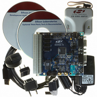
DEV KIT FOR F060/F062/F063
Manufacturer
Silicon Laboratories Inc
Type
MCUr
Datasheet
1.C8051F060-TB.pdf
(328 pages)
Specifications of C8051F060DK
Contents
Evaluation Board, Power Supply, USB Cables, Adapter and Documentation
Processor To Be Evaluated
C8051F06x
Interface Type
USB
Silicon Manufacturer
Silicon Labs
Core Architecture
8051
Silicon Core Number
C8051F060
Silicon Family Name
C8051F06x
Lead Free Status / RoHS Status
Contains lead / RoHS non-compliant
For Use With/related Products
C8051060, C8051F062 and C8051F063
Lead Free Status / Rohs Status
Lead free / RoHS Compliant
Other names
336-1214
Available stocks
Company
Part Number
Manufacturer
Quantity
Price
Company:

Part Number:
C8051F060DK
Manufacturer:
Silicon Labs
Quantity:
135


C8051F060/1/2/3/4/5/6/7
The temperature sensor connects to the highest order input of the ADC2 input multiplexer (see
“7. 10-Bit ADC (ADC2, C8051F060/1/2/3)” on page
ables the temperature sensor. While disabled, the temperature sensor defaults to a high impedance state,
and any A/D measurements performed on the sensor while disabled result in meaningless data.
112
VDD = 3.0 V, AV+ = 3.0 V, -40 to +85 °C unless otherwise specified
Parameter
Internal Reference (REFBE = 1)
Output Voltage
VREF Power Supply Current
VREF Short-Circuit Current
VREF Temperature Coefficient
Load Regulation
VREF Turn-on Time 1
VREF Turn-on Time 2
VREF Turn-on Time 3
External Reference (REFBE = 0)
Input Voltage Range
Input Current
Bits7-4:
Bit3:
Bit2:
Bit1:
Bit0:
R/W
Bit7
-
UNUSED. Read = 0000b; Write = don’t care.
AD2VRS: ADC2 Voltage Reference Select.
0: ADC2 voltage reference from VREF2 pin.
1: ADC2 voltage reference from AV+.
TEMPE: Temperature Sensor Enable Bit.
0: Internal Temperature Sensor Off.
1: Internal Temperature Sensor On.
BIASE: ADC/DAC Bias Generator Enable Bit. (Must be ‘1’ if using ADC2 or DACs).
0: Internal Bias Generator Off.
1: Internal Bias Generator On.
REFBE: Internal Reference Buffer Enable Bit.
0: Internal Reference Buffer Off.
1: Internal Reference Buffer On. Internal voltage reference is driven on the VREF pin.
R/W
Bit6
-
Table 9.1. Voltage Reference Electrical Characteristics
Figure 9.2. REF2CN: Reference Control Register 2
R/W
Bit5
-
Conditions
25 °C ambient
Load = 0 to 200 µA to AGND
4.7 µF tantalum, 0.1 µF ceramic
bypass
0.1 µF ceramic bypass
no bypass cap
R/W
Bit4
-
AD2VRS
Rev. 1.2
R/W
Bit3
87). The TEMPE bit within REF2CN enables and dis-
TEMPE
R/W
Bit2
2.36
1.00
Min
BIASE
R/W
Bit1
2.43
Typ
0.5
50
15
20
10
2
0
SFR Address:
REFBE
SFR Page:
R/W
Bit0
(AV+) -
Max
2.48
30
0.3
1
0xD1
2
Reset Value
00000000
ppm/µA
ppm/°C
Units
mA
Section
µA
ms
µA
µs
µs
V
V
Related parts for C8051F060DK
Image
Part Number
Description
Manufacturer
Datasheet
Request
R

Part Number:
Description:
SMD/C°/SINGLE-ENDED OUTPUT SILICON OSCILLATOR
Manufacturer:
Silicon Laboratories Inc
Part Number:
Description:
Manufacturer:
Silicon Laboratories Inc
Datasheet:
Part Number:
Description:
N/A N/A/SI4010 AES KEYFOB DEMO WITH LCD RX
Manufacturer:
Silicon Laboratories Inc
Datasheet:
Part Number:
Description:
N/A N/A/SI4010 SIMPLIFIED KEY FOB DEMO WITH LED RX
Manufacturer:
Silicon Laboratories Inc
Datasheet:
Part Number:
Description:
N/A/-40 TO 85 OC/EZLINK MODULE; F930/4432 HIGH BAND (REV E/B1)
Manufacturer:
Silicon Laboratories Inc
Part Number:
Description:
EZLink Module; F930/4432 Low Band (rev e/B1)
Manufacturer:
Silicon Laboratories Inc
Part Number:
Description:
I°/4460 10 DBM RADIO TEST CARD 434 MHZ
Manufacturer:
Silicon Laboratories Inc
Part Number:
Description:
I°/4461 14 DBM RADIO TEST CARD 868 MHZ
Manufacturer:
Silicon Laboratories Inc
Part Number:
Description:
I°/4463 20 DBM RFSWITCH RADIO TEST CARD 460 MHZ
Manufacturer:
Silicon Laboratories Inc
Part Number:
Description:
I°/4463 20 DBM RADIO TEST CARD 868 MHZ
Manufacturer:
Silicon Laboratories Inc
Part Number:
Description:
I°/4463 27 DBM RADIO TEST CARD 868 MHZ
Manufacturer:
Silicon Laboratories Inc
Part Number:
Description:
I°/4463 SKYWORKS 30 DBM RADIO TEST CARD 915 MHZ
Manufacturer:
Silicon Laboratories Inc
Part Number:
Description:
N/A N/A/-40 TO 85 OC/4463 RFMD 30 DBM RADIO TEST CARD 915 MHZ
Manufacturer:
Silicon Laboratories Inc
Part Number:
Description:
I°/4463 20 DBM RADIO TEST CARD 169 MHZ
Manufacturer:
Silicon Laboratories Inc