C8051F060DK Silicon Laboratories Inc, C8051F060DK Datasheet - Page 229
C8051F060DK
Manufacturer Part Number
C8051F060DK
Description
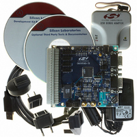
DEV KIT FOR F060/F062/F063
Manufacturer
Silicon Laboratories Inc
Type
MCUr
Datasheet
1.C8051F060-TB.pdf
(328 pages)
Specifications of C8051F060DK
Contents
Evaluation Board, Power Supply, USB Cables, Adapter and Documentation
Processor To Be Evaluated
C8051F06x
Interface Type
USB
Silicon Manufacturer
Silicon Labs
Core Architecture
8051
Silicon Core Number
C8051F060
Silicon Family Name
C8051F06x
Lead Free Status / RoHS Status
Contains lead / RoHS non-compliant
For Use With/related Products
C8051060, C8051F062 and C8051F063
Lead Free Status / Rohs Status
Lead free / RoHS Compliant
Other names
336-1214
Available stocks
Company
Part Number
Manufacturer
Quantity
Price
Company:

Part Number:
C8051F060DK
Manufacturer:
Silicon Labs
Quantity:
135


Please refer to the Bosch CAN User’s Guide for information on the function and use of the Mes-
sage Handler Registers.
19.2.4. CIP-51 MCU Special Function Registers
C8051F060/1/2/3 peripherals are modified, monitored, and controlled using Special Function Registers
(SFRs). Most of the CAN Controller registers cannot be accessed directly using the SFRs. Three of the
CAN Controller’s registers may be accessed directly with SFRs. All other CAN Controller registers are
accessed indirectly using three CIP-51 MCU SFRs: the CAN Data Registers (CAN0DATH and
CAN0DATL) and CAN Address Register (CAN0ADR). In this way, there are a total of five CAN registers
used to configure and run the CAN Controller.
19.2.5. Using CAN0ADR, CAN0DATH, and CANDATL To Access CAN Registers
Each CAN Controller Register has an index number (see Table below). The CAN register address space
is 128 words (256 bytes). A CAN register is accessed via the CAN Data Registers (CAN0DATH and
CAN0DATL) when a CAN register’s index number is placed into the CAN Address Register (CAN0ADR).
For example, if the Bit Timing Register is to be configured with a new value, CAN0ADR is loaded with
0x03. The low byte of the desired value is accessed using CAN0DATL and the high byte of the bit timing
register is accessed using CAN0DATH. CAN0DATL is bit addressable for convenience. To load the value
0x2304 into the Bit Timing Register:
Note: CAN0CN, CAN0STA, and CAN0TST may be accessed either by using the index method, or by direct
access with the CIP-51 MCU SFRs. CAN0CN is located at SFR location 0xF8/SFR page 1 (Figure 19.6),
CAN0TST at 0xDB/SFR page 1 (Figure 19.7), and CAN0STA at 0xC0/SFR page 1 (Figure 19.8).
19.2.6. CAN0ADR Autoincrement Feature
For ease of programming message objects, CAN0ADR features autoincrementing for the index ranges
0x08 to 0x12 (Interface Registers 1) and 0x20 to 0x2A (Interface Registers 2). When the CAN0ADR regis-
ter has an index in these ranges, the CAN0ADR will autoincrement by 1 to point to the next CAN reg-
ister 16-bit word upon a read/write of CAN0DATL. This speeds programming of the frequently
programmed interface registers when configuring message objects.
NOTE: Table below supersedes Figure 5 in section 3, “Programmer’s Model” of the Bosch CAN
User’s Guide.
CAN Register
CAN0ADR = 0x03;
CAN0DATH = 0x23;
CAN0DATL = 0x04;
Index
0x00
0x01
0x02
0x03
CAN Control Register
Bit Timing Register
Register name
Status Register
Error Register
Table 19.1. CAN Register Index and Reset Values
// Load Bit Timing Register’s index (Table 18.1)
// Move the upper byte into data reg high byte
// Move the lower byte into data reg low byte
0x0001 Accessible in CIP-51 SFR Map
0x0000 Accessible in CIP-51 SFR Map
0x0000 Read Only
0x2301 Write Enabled by CCE Bit in CAN0CN
Reset
Value
Rev. 1.2
C8051F060/1/2/3/4/5/6/7
Notes
229
Related parts for C8051F060DK
Image
Part Number
Description
Manufacturer
Datasheet
Request
R

Part Number:
Description:
SMD/C°/SINGLE-ENDED OUTPUT SILICON OSCILLATOR
Manufacturer:
Silicon Laboratories Inc
Part Number:
Description:
Manufacturer:
Silicon Laboratories Inc
Datasheet:
Part Number:
Description:
N/A N/A/SI4010 AES KEYFOB DEMO WITH LCD RX
Manufacturer:
Silicon Laboratories Inc
Datasheet:
Part Number:
Description:
N/A N/A/SI4010 SIMPLIFIED KEY FOB DEMO WITH LED RX
Manufacturer:
Silicon Laboratories Inc
Datasheet:
Part Number:
Description:
N/A/-40 TO 85 OC/EZLINK MODULE; F930/4432 HIGH BAND (REV E/B1)
Manufacturer:
Silicon Laboratories Inc
Part Number:
Description:
EZLink Module; F930/4432 Low Band (rev e/B1)
Manufacturer:
Silicon Laboratories Inc
Part Number:
Description:
I°/4460 10 DBM RADIO TEST CARD 434 MHZ
Manufacturer:
Silicon Laboratories Inc
Part Number:
Description:
I°/4461 14 DBM RADIO TEST CARD 868 MHZ
Manufacturer:
Silicon Laboratories Inc
Part Number:
Description:
I°/4463 20 DBM RFSWITCH RADIO TEST CARD 460 MHZ
Manufacturer:
Silicon Laboratories Inc
Part Number:
Description:
I°/4463 20 DBM RADIO TEST CARD 868 MHZ
Manufacturer:
Silicon Laboratories Inc
Part Number:
Description:
I°/4463 27 DBM RADIO TEST CARD 868 MHZ
Manufacturer:
Silicon Laboratories Inc
Part Number:
Description:
I°/4463 SKYWORKS 30 DBM RADIO TEST CARD 915 MHZ
Manufacturer:
Silicon Laboratories Inc
Part Number:
Description:
N/A N/A/-40 TO 85 OC/4463 RFMD 30 DBM RADIO TEST CARD 915 MHZ
Manufacturer:
Silicon Laboratories Inc
Part Number:
Description:
I°/4463 20 DBM RADIO TEST CARD 169 MHZ
Manufacturer:
Silicon Laboratories Inc