C8051F060DK Silicon Laboratories Inc, C8051F060DK Datasheet - Page 53
C8051F060DK
Manufacturer Part Number
C8051F060DK
Description
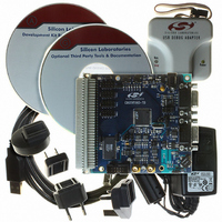
DEV KIT FOR F060/F062/F063
Manufacturer
Silicon Laboratories Inc
Type
MCUr
Datasheet
1.C8051F060-TB.pdf
(328 pages)
Specifications of C8051F060DK
Contents
Evaluation Board, Power Supply, USB Cables, Adapter and Documentation
Processor To Be Evaluated
C8051F06x
Interface Type
USB
Silicon Manufacturer
Silicon Labs
Core Architecture
8051
Silicon Core Number
C8051F060
Silicon Family Name
C8051F06x
Lead Free Status / RoHS Status
Contains lead / RoHS non-compliant
For Use With/related Products
C8051060, C8051F062 and C8051F063
Lead Free Status / Rohs Status
Lead free / RoHS Compliant
Other names
336-1214
Available stocks
Company
Part Number
Manufacturer
Quantity
Price
Company:

Part Number:
C8051F060DK
Manufacturer:
Silicon Labs
Quantity:
135


5.2.
The voltage reference circuitries for ADC0 and ADC1 allow for many different voltage reference configura-
tions. Each ADC has the capability to use its own dedicated, on-chip voltage reference, or an off-chip refer-
ence circuit. A block diagram of the reference circuitry for one ADC is shown in Figure 5.3.
The internal voltage reference circuit for each ADC consists of an independent, temperature stable 1.2 V
bandgap voltage reference generator, with an output buffer amplifier which multiplies the bandgap refer-
ence by 2. The maximum load seen by the VREFn (VREF0 or VREF1) pin must be less than 100 µA to
AGND. Bypass capacitors of 0.1 µF and 47 µF are recommended from the VREFn pin to VRGNDn.
The voltage reference circuitry for each ADC is controlled in the Reference Control Registers. REF0CN
(defined in Figure 5.11) is the Reference Control Register for ADC0, and REF1CN (defined in Figure 5.12)
is the Reference Control Register for ADC1. The REFnCN registers are used to enable/disable the internal
reference and bias generator circuitry for each ADC independently. The BIASEn bits enable the on-board
bias generators for each ADC, while the REFBEn bits enable the 2x buffer amplifiers which drive the
VREFn pins. When disabled, the supply current drawn by the bandgap and buffer amplifier falls to less
than 1 µA (typical) and the output of the buffer amplifier enters a high impedance state (approximately 25 k
Ohms). If the internal voltage reference for an ADC is used, the BIASEn and REFBEn bits for that ADC
must both be set to logic 1. If an external reference is used, the REFBEn bit should be set to logic 0. Note
that the BIASEn bit for an ADC must be set to logic 1 to enable that ADC, regardless of the voltage refer-
ence that is used. If an ADC is not being used, the BIASEn bit can be set to logic 0 to conserve power. The
electrical specifications for the Voltage References are given in Table 5.3.
47F
Bypass Capacitors
Reference
Recommended
Voltage Reference
External
Voltage
0.1F
0.1F
VRGNDn
VBGAPn
VREFn
Figure 5.3. Voltage Reference Block Diagram
Ref
ADCn
Rev. 1.2
Bias
C8051F060/1/2/3/4/5/6/7
x2
Band-Gap
REFnCN
1.25V
EN
53
Related parts for C8051F060DK
Image
Part Number
Description
Manufacturer
Datasheet
Request
R

Part Number:
Description:
SMD/C°/SINGLE-ENDED OUTPUT SILICON OSCILLATOR
Manufacturer:
Silicon Laboratories Inc
Part Number:
Description:
Manufacturer:
Silicon Laboratories Inc
Datasheet:
Part Number:
Description:
N/A N/A/SI4010 AES KEYFOB DEMO WITH LCD RX
Manufacturer:
Silicon Laboratories Inc
Datasheet:
Part Number:
Description:
N/A N/A/SI4010 SIMPLIFIED KEY FOB DEMO WITH LED RX
Manufacturer:
Silicon Laboratories Inc
Datasheet:
Part Number:
Description:
N/A/-40 TO 85 OC/EZLINK MODULE; F930/4432 HIGH BAND (REV E/B1)
Manufacturer:
Silicon Laboratories Inc
Part Number:
Description:
EZLink Module; F930/4432 Low Band (rev e/B1)
Manufacturer:
Silicon Laboratories Inc
Part Number:
Description:
I°/4460 10 DBM RADIO TEST CARD 434 MHZ
Manufacturer:
Silicon Laboratories Inc
Part Number:
Description:
I°/4461 14 DBM RADIO TEST CARD 868 MHZ
Manufacturer:
Silicon Laboratories Inc
Part Number:
Description:
I°/4463 20 DBM RFSWITCH RADIO TEST CARD 460 MHZ
Manufacturer:
Silicon Laboratories Inc
Part Number:
Description:
I°/4463 20 DBM RADIO TEST CARD 868 MHZ
Manufacturer:
Silicon Laboratories Inc
Part Number:
Description:
I°/4463 27 DBM RADIO TEST CARD 868 MHZ
Manufacturer:
Silicon Laboratories Inc
Part Number:
Description:
I°/4463 SKYWORKS 30 DBM RADIO TEST CARD 915 MHZ
Manufacturer:
Silicon Laboratories Inc
Part Number:
Description:
N/A N/A/-40 TO 85 OC/4463 RFMD 30 DBM RADIO TEST CARD 915 MHZ
Manufacturer:
Silicon Laboratories Inc
Part Number:
Description:
I°/4463 20 DBM RADIO TEST CARD 169 MHZ
Manufacturer:
Silicon Laboratories Inc