MPC8349E-MITXE Freescale Semiconductor, MPC8349E-MITXE Datasheet - Page 27
MPC8349E-MITXE
Manufacturer Part Number
MPC8349E-MITXE
Description
BOARD REFERENCE FOR MPC8349
Manufacturer
Freescale Semiconductor
Series
PowerQUICC II™ PROr
Type
MPUr
Specifications of MPC8349E-MITXE
Contents
Module and Misc Hardware
Processor To Be Evaluated
MPC8349E
Interface Type
Ethernet, USB
Silicon Manufacturer
Freescale
Core Architecture
Power Architecture
Core Sub-architecture
PowerQUICC
Silicon Core Number
MPC83xx
Silicon Family Name
PowerQUICC II PRO
Rohs Compliant
Yes
For Use With/related Products
MPC8349E
Lead Free Status / RoHS Status
Lead free / RoHS Compliant
Other names
MPC8349E-MITXE


1.4.12
The 5 V LCD backlight connector (J16) is for typical LCD backlights. The +5 V is labelled with a plus (+)
sign, and the GND is labelled with a minus (–) sign on the board.
1.4.13
J4 is the 6-pin dual in-line 68HCS08 BDM (background debug mode) interface header for programming
the MC9S08QG8 microcontroller. You can use either the PC-based USBMULTILINKBDM or the
standalone M68CYCLONEPRO in-circuit debugger/programmer interfaces.
1.4.14
Two MCU GPIO connectors (J15, J18) serve as general-purpose I/O controlled by the MCU.
1.4.15
P18 is compatible with connectors from ATX power supply, supplying necessary DC power to the
MPC8349E-mITXE board.
1.5
This section shows the default settings and descriptions of jumpers, switches, and LED indicators.
1.5.1
The powerup configuration jumpers at J22 sets up the system configurations.
default configuration of J22.
Freescale Semiconductor
Jumpers, Switches, and LED Indicators
LCD Backlight Connector
MCU Debug Port (J4)
MCU GPIO Connector
Power Connector
Powerup Configuration Jumpers
Jumper On
MPC8349E-mITXE Reference Design Platform User’s Guide, Rev. 2
Figure 23. Powerup Configuration Jumpers (J22)
A
Preliminary—Subject to Change Without Notice
B
C
D
E
F
G
H
Jumper Off
Figure 23
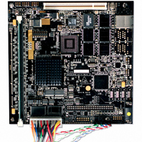
MPC8349E-mITXE Board
shows the factory
27
Related parts for MPC8349E-MITXE
Image
Part Number
Description
Manufacturer
Datasheet
Request
R

Part Number:
Description:
KIT REFERENCE PLATFORM MPC8349E
Manufacturer:
Freescale Semiconductor
Datasheet:
Part Number:
Description:
KIT MODULAR DEV SYSTEM MPC8349E
Manufacturer:
Freescale Semiconductor
Datasheet:

Part Number:
Description:
MCU, MPU & DSP Development Tools PROCESSR BD MPC8349E
Manufacturer:
Freescale Semiconductor
Part Number:
Description:
MCU, MPU & DSP Development Tools KIT FOR MPC8349E BDS
Manufacturer:
Freescale Semiconductor

Part Number:
Description:
Manufacturer:
Freescale Semiconductor, Inc
Datasheet:
Part Number:
Description:
Manufacturer:
Freescale Semiconductor, Inc
Datasheet:
Part Number:
Description:
Manufacturer:
Freescale Semiconductor, Inc
Datasheet:
Part Number:
Description:
Manufacturer:
Freescale Semiconductor, Inc
Datasheet:
Part Number:
Description:
Manufacturer:
Freescale Semiconductor, Inc
Datasheet:
Part Number:
Description:
Manufacturer:
Freescale Semiconductor, Inc
Datasheet:
Part Number:
Description:
Manufacturer:
Freescale Semiconductor, Inc
Datasheet:
Part Number:
Description:
Manufacturer:
Freescale Semiconductor, Inc
Datasheet:
Part Number:
Description:
Manufacturer:
Freescale Semiconductor, Inc
Datasheet:
Part Number:
Description:
Manufacturer:
Freescale Semiconductor, Inc
Datasheet:
Part Number:
Description:
Manufacturer:
Freescale Semiconductor, Inc
Datasheet: