HW-V5-ML506-UNI-G Xilinx Inc, HW-V5-ML506-UNI-G Datasheet - Page 44
HW-V5-ML506-UNI-G
Manufacturer Part Number
HW-V5-ML506-UNI-G
Description
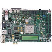
EVALUATION PLATFORM VIRTEX-5
Manufacturer
Xilinx Inc
Series
Virtex™-5 SXTr
Type
DSPr
Datasheet
1.HW-V5-ML507-UNI-G.pdf
(60 pages)
Specifications of HW-V5-ML506-UNI-G
Contents
Evaluation Platform, DVI Adapter and CompactFlash Card
Silicon Manufacturer
Xilinx
Features
JTAG Programming Interface, Platform Flash, External Clocking
Kit Contents
Board, Cable, PSU, CD, Docs
Silicon Family Name
Virtex-5
Silicon Core Number
XC5VSX50TFFG1136
Rohs Compliant
Yes
Lead Free Status / RoHS Status
Lead free / RoHS Compliant
For Use With/related Products
XC5VSX50TFFG1136
Lead Free Status / RoHS Status
Lead free / RoHS Compliant, Lead free / RoHS Compliant
Available stocks
Company
Part Number
Manufacturer
Quantity
Price


Chapter 1: ML505/ML506/ML507 Evaluation Platform
44
41. Serial-ATA Host Connectors
42. SFP Connector
Serial-ATA (SATA) is the next generation of the ATA interface used for storage devices
such as hard disks. The board contains two SATA host connectors that can be connected to
a SATA device (such as a hard disk) using a standard SATA cable. The SATA connectors
are connected to GTPs on the FPGA as shown in
Table 1-26: SATA Connections
SATA can also be used as a convenient and low cost medium for connecting GTP/GTX
transceivers. The SATA physical interface can carry GTP/GTX signals up to 1.5 Gb/s for
general-purpose usage. The board ships with a special Xilinx SATA crossover cable that is
used as a loopback connection between the two SATA host connectors for loopback testing
and bit error rate testing (BERT). The SATA crossover cable can also be used to connect
GTP/GTX transceivers between two boards. For GTP/GTX SATA clock jumpering, see
Figure 1-4, page
Note:
(that is, PC to hard disk). It is only intended for host-to-host loopback connections.
The board contains a small form-factor pluggable (SFP) connector and cage assembly that
accepts SFP modules. The SFP interface is connected to GTP0 of GTP_X0Y4 on the FPGA.
The SFP module serial ID interface is connected to the IIC multiplexer on the board (See
“14. IIC Bus with 8-Kb EEPROM,” page 27
signals for the SFP module are connected to jumpers, test points, and LEDs as described in
Table
SATA1_RX_N
SATA2_RX_N
SATA1_TX_N
SATA2_TX_N
SATA1_RX_P
SATA2_RX_P
SATA1_TX_P
SATA2_TX_P
Pin Name
1-27. The SFP module connections are shown in
The special SATA crossover cable cannot be used to connect a SATA host to a SATA device
32.
FPGA Pin (U1) Connector Pin
AA1
AC2
AB1
AB2
W1
W2
Y1
V2
www.xilinx.com
J40, pin 5
J40, pin 6
J40, pin 2
J40, pin 3
J41, pin 6
J41, pin 5
J41, pin 2
J41, pin 3
for more information). The control and status
Table
ML505/ML506/ML507 Evaluation Platform
GTP0 of
GTP_X0Y2
receive pair
GTP0 of
GTP_X0Y2
transmit pair
GTP1 of
GTP_X0Y2
receive pair
GTP1 of
GTP_X0Y2
transmit pair
ML505/ML506
Table 1-28, page
1-26.
UG347 (v3.1.1) October 7, 2009
GTX0 of
GTX_X0Y3
receive pair
GTX0 of
GTX_X0Y3
transmit pair
GTX1 of
GTX_X0Y3
receive pair
GTX1 of
GTX_X0Y3
transmit pair
45.
ML507
R
Related parts for HW-V5-ML506-UNI-G
Image
Part Number
Description
Manufacturer
Datasheet
Request
R

Part Number:
Description:
IC CPLD .8K 36MCELL 44-VQFP
Manufacturer:
Xilinx Inc
Datasheet:

Part Number:
Description:
IC CPLD 72MCRCELL 10NS 44VQFP
Manufacturer:
Xilinx Inc
Datasheet:

Part Number:
Description:
IC CPLD 1.6K 72MCELL 64-VQFP
Manufacturer:
Xilinx Inc
Datasheet:

Part Number:
Description:
IC CR-II CPLD 64MCELL 44-VQFP
Manufacturer:
Xilinx Inc
Datasheet:

Part Number:
Description:
IC CPLD 1.6K 72MCELL 100-TQFP
Manufacturer:
Xilinx Inc
Datasheet:

Part Number:
Description:
IC CR-II CPLD 64MCELL 56-BGA
Manufacturer:
Xilinx Inc
Datasheet:

Part Number:
Description:
IC CPLD 72MCRCELL 7.5NS 44VQFP
Manufacturer:
Xilinx Inc
Datasheet:
Part Number:
Description:
IC CR-II CPLD 64MCELL 100-VQFP
Manufacturer:
Xilinx Inc
Datasheet:
Part Number:
Description:
IC CPLD 1.6K 72MCELL 100-TQFP
Manufacturer:
Xilinx Inc
Datasheet:

Part Number:
Description:
IC CPLD 72MCRCELL 7.5NS 64VQFP
Manufacturer:
Xilinx Inc
Datasheet:
Part Number:
Description:
IC CPLD 1.6K 72MCELL 100-TQFP
Manufacturer:
Xilinx Inc
Datasheet:

Part Number:
Description:
IC CPLD 1.5K 64MCELL HP 44-VQFP
Manufacturer:
Xilinx Inc

Part Number:
Description:
IC CPLD 36MCRCELL 15NS 44PLCC
Manufacturer:
Xilinx Inc
Datasheet:

Part Number:
Description:
IC CPLD 36MCRCELL 10NS 44PLCC
Manufacturer:
Xilinx Inc
Datasheet:

Part Number:
Description:
IC CPLD 1.5K 64MCELL HP 44-VQFP
Manufacturer:
Xilinx Inc