ATAVRONEKIT Atmel, ATAVRONEKIT Datasheet
ATAVRONEKIT
Specifications of ATAVRONEKIT
Available stocks


Related parts for ATAVRONEKIT


ATAVRONEKIT Summary of contents
Page 1
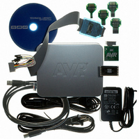
AVR ONE! .................................................................................................................... Quick-start Guide ® EVK1101 + Windows 32104B–AVR ONE!–02/10 ...
Page 2
Section 1 Introduction................................................................................................................. 1-1 1.1 General .............................................................................................................................. 1-1 1.2 Requirements..................................................................................................................... 1-1 Section 2 Quick-start guide (short version) ................................................................................ 2-1 2.1 Install Hardware and software ........................................................................................... 2-1 2.2 Create a demonstration project ......................................................................................... 2-1 2.3 Configure target MCU for a debug ...
Page 3
Modify the application ...................................................................................................... 6-27 Section 6 Firmware Upgrade...................................................................................................... 7-1 6.1 Firmware upgrade overview............................................................................................... 7-1 6.2 Firmware version test and upgrade ................................................................................... 7-1 6.3 Adapter in use.................................................................................................................... 7-2 AVR ONE! Quick-start Guide Table of Contents (Continued) ii 32104B–AVR ONE!–02/10 ...
Page 4
... AVR32 Studio. In addition to the AVR ONE! debugger, you need the following items: – AVR32 Studio 2.5 software – AVR32 GNU Toolchain 2.4 – EVK110x Evaluation board Software and documents can be found at www.atmel.com/avrone 1.2 Requirements This example was created running Microsoft Windows, the behaviour when installing software and drivers may be slightly different ...
Page 5
Install Hardware and software Download and install avr32-gnu-toolchain-2.4.x and AVR32Studio-2.5.x. Connect AVR ONE! to power and USB and turn it on. Install AVR ONE! USB driver. Connect AVR ONE! to the EVK1101 using the 10pin JTAG connector. Connect the ...
Page 6
Start the debug session and configure AVR32 Studio 2.5 for trace Click the Debug-button. Now the program will be loaded into the target, and run until main(). When the program halts, add at least a trace start-point (Right-click to ...
Page 7
Download the software To use the AVR ONE!, you must download and install two software packages: avr32-gnu-toolchain-2.4.x.exe AVR32Studio-2.5.x.exe The AVR32 Toolchain is a collection of tools that are required to be able to work with the AVR ONE! It ...
Page 8
... Download the two installation files to your disk. The installation files can be found at this location: www.atmel.com/avrone 3.3 Install AVR32 GNU Toolchain If you have any AVR tools connected to the USB hub, turn them off now. Otherwise the USB driver installation may fail. ...
Page 9
Figure 3-3. AVR32 GNU Toolchain License Agreement form Select I accept the terms of the licence agreement, then click Next. Figure 3-4. AVR32 GNU Toolchain installation folder select Check that the installation folder is correct and click Next. AVR ONE! ...
Page 10
Figure 3-5. AVR32 GNU Toolchain installer configuration finished Click Install. Figure 3-6. AVR32 GNU Toolchain installation progress indicator The AVR32 GNU Toolchain is now being installed part of the installation process, USB drivers for all supported programming and ...
Page 11
Figure 3-7. USB Drivers installation start Figure 3-8. USB Driver installer welcome Click Next. AVR ONE! Quick-start Guide Software Installation 4-5 32104B–AVR ONE!–02/10 ...
Page 12
Figure 3-9. USB Drivers licence agreement form Select I accept the terms of the licence agreement, then click Next. Figure 3-10. USB drivers installer configuration finished Click Install. AVR ONE! Quick-start Guide Software Installation 4-6 32104B–AVR ONE!–02/10 ...
Page 13
Figure 3-11. USB Drivers installation progress indicator Figure 3-12. USB Drivers installation complete Click Finish. AVR ONE! Quick-start Guide Software Installation 4-7 32104B–AVR ONE!–02/10 ...
Page 14
Figure 3-13. AVR32 GNU Toolchain installation complete Click Finish to complete the AVR32 Toolchain installation process. 3.4 Install AVR32 Studio 2.5 Double-click on the AVR32Studio-2.5.x.exe file to start the installation process. Figure 3-14. AVR32 Studio 2.5 installer welcome Click Next. ...
Page 15
Figure 3-15. AVR32 Studio installation folder select Check that the installation folder is correct and click Next. Figure 3-16. AVR32 Studio installer configuration finished Click Install to start the installation. AVR ONE! Quick-start Guide Software Installation 4-9 32104B–AVR ONE!–02/10 ...
Page 16
Figure 3-17. AVR32 Studio installation progress indicator Wait for the installation process to complete suitable Java™ runtime is not installed, a Java installer wizard will guide you through the installation procedure. Figure 3-18. AVR32 Studio installation process complete ...
Page 17
Connect the AVR ONE! to power and USB host Connect the AVR ONE! to power using the supplied power supply. Connect the AVR ONE! to the USB host (PC) using the supplied USB cable Turn on the AVR ONE! ...
Page 18
... AVR ONE! is connected to the PC, even if the driver is the same as for all other AVR ONE!s that have been connected previously. This is a property of the operating system, and is not controlled by any Atmel software installed. Figure 3-20. “New hardware” notification pop-up Figure 3-21 ...
Page 19
Figure 3-22. Hardware installation wizard configuration Select Install the software automatically and click Next. Figure 3-23. Hardware installation in progress Wait for the installation process to complete. AVR ONE! Quick-start Guide Software Installation 4-13 32104B–AVR ONE!–02/10 ...
Page 20
Figure 3-24. Hardware installation wizard complete Click Finish. AVR ONE! Quick-start Guide Software Installation 4-14 32104B–AVR ONE!–02/10 ...
Page 21
Connect the AVR ONE! to the EVK1101 Connect the AVR ONE! debugger to the EVK1101 evaluation board using the 10 pin JTAG connector. To make it possible to use the joystick while the AVR ONE! is connected to the ...
Page 22
Connect the EVK1101 to power and RS232 Connect the EVK1101 to power and turn it on. The easiest way to provide power is to use the supplied USB cable. Also connect the RS232 port to your PC using the ...
Page 23
Start AVR32 Studio Start AVR32 Studio. Start-up may take a while (because of all the Java libraries being loaded). Figure 5-1. AVR32 Studio splash screen Figure 5-2. AVR32 Studio workspace selection Select a suitable workspace folder for your project ...
Page 24
Figure 5-3. AVR32 Studio Welcome view Exit from the welcome screen to the workbench by clicking on the Close Page icon (Arrow). 5.2 Configure adapter and target Before you can use the AVR ONE! and the EVK1101, you have to ...
Page 25
Add and configure the adapter (AVR ONE!) Figure 5-4. Scan Targets Right-click in the AVR32 Target-view and select Scan Targets. Figure 5-5. Available targets Select the AVR ONE! Figure 5-6. Selecting the properties view Click on the Properties tab. ...
Page 26
Configure target board and MCU Figure 5-7. Details configuration tab Set Device to UC3B0256 or UC3B0256ES, depending on what MCU is installed on your EVK1101. Figure 5-8. MCU Markings To check which type of MCU is mounted on your ...
Page 27
Target MCU Chip erase If the EVK1101 evaluation board is brand new still contains the original demo application (Control Panel Demo), the FLASH lock-bits need to be cleared. Right-click on the AVR ONE! In the AVR32 ...
Page 28
Create a demonstration project Figure 5-10. Create new project Create a new project by clicking File>New>AVR32 Example Project. Figure 5-11. Select project example Select EVK1101 – Components - Accelerometer example, then click Next AVR ONE! Quick-start Guide Create demo ...
Page 29
Figure 5-12. New project name Enter a name for the project, and click Finish. AVR ONE! Quick-start Guide Create demo application 6-7 32104B–AVR ONE!–02/10 ...
Page 30
Figure 5-13. Build project Right-click on the project in Project Explorer-view and select Build Project (or press CTRL+B). Figure 5-14. Project build progress Wait for the project build process to finish. AVR ONE! Quick-start Guide Create demo application 6-8 32104B–AVR ...
Page 31
Figure 5-15. Console view The console shows output from the compiler. Make sure that this ends with a “Build complete ...” mes- sage (Except for the “Time consumed” message). If something is not working, you will see error messages in ...
Page 32
Create a new debug launch configuration In the Debug Configurations view, select AVR32 Application and right click and select New. A new launch configuration will be created and default values will be filled into all applicable fields. Select the ...
Page 33
Configure the target trace module for program trace Figure 5-18. Debug configurations, Main tab In the Main tab, make sure that Target is set to AVR ONE! Figure 5-19. Debug configurations, Debugger tab Select the Debugger tab and check ...
Page 34
Figure 5-20. Enable Trace Select the Trace tab and check Enable Trace. Figure 5-21. Preferred Trace method Select the preferred trace method. In this case we want Nano Trace. Deselect Break on application buffer access. AVR ONE! Quick-start Guide Create ...
Page 35
Figure 5-22. Trace buffer size Select Specify size and location option. Then click Detect to configure trace buffer size and location. Figure 5-23. Buffer full action Selected the preferred action when buffer is full. In this case we choose Break, ...
Page 36
Configure the target trace module for data trace We would like to trace all data written to the debug UART quick lookup in the datasheet and find that the UART registers are located between 0xffff1400 and ...
Page 37
Figure 5-27. Configured trace AVR ONE! Quick-start Guide Create demo application 6-15 32104B–AVR ONE!–02/10 ...
Page 38
Start a debug session and configure the debugger for trace Click the Debug button in the Debug Confugurations view. Now the program will be loaded into the target, and run until main(). Figure 5-28. Switching perspective When the debug ...
Page 39
Add start and stop trace-points Figure 5-30. Source code editor Scroll up to line 156 in the file acc_example.c and right-click at the left edge of the editor. Select Add Tracepoint... from the pop-up menu. AVR ONE! Quick-start Guide ...
Page 40
Figure 5-31. Tracepoint (Start) Set Tracepoint Configuration values: – Set Trigger Event to Program Counter – Set Trace Operation to Start Trace – Set Tracepoint type to both Program trace and Data trace – Click OK This will create a ...
Page 41
Figure 5-32. Tracepoint (Stop) Set Tracepoint Configuration values: – Set Trigger Event to Program Counter – Set Trace Operation to Stop Trace – Set Tracepoint type to both Program trace and Data trace – Click OK This will create a ...
Page 42
Start the trace debug session Figure 5-33. Resume debug session Make sure that the main() process is still selected in the Debug view before pressing the Resume button. Start a serial port terminal to view the output from the ...
Page 43
Figure 5-35. Hyperterminal port selection Seletc the com-port that you connected the EVK1101 to (in this case we use Com1). Figure 5-36. Hyperterminal port configuration Set port parameters: – Bits per second: 57600 – Data bits: 8 – Parity: None ...
Page 44
Figure 5-37. Demo application output Tilt the EVK1101 board carefully as shown in the photograph. Start with the board laying flat on the table, and increase the tilt slowly. Figure 5-38. Tilting the EVK1101 board AVR ONE! Quick-start Guide Create ...
Page 45
When the tilting angle reaches a certain value, the debug output notifies you about which direction the board is being tilted. Figure 5-39. Tilt direction indicator When the tilt angle reaches 30 degrees, the program wants to print an additional ...
Page 46
Figure 5-40. Debug output stopped when trace buffer full When the trace buffer in the target MCU is full, the program will break, and trace data will be uploaded to AVR32 Studio for inspection. 5.8 View trace data Figure 5-41. ...
Page 47
Figure 5-42. Reconstructed source code Click on a trace frame to view the reconstructed code that was executed by the MCU. Figure 5-43. Data trace frame A data trace frame showing a byte being written to the debug UART transmit ...
Page 48
Figure 5-44. Source code in editor Double-click on a trace frame to show the source code in the editor. AVR ONE! Quick-start Guide Create demo application 6-26 32104B–AVR ONE!–02/10 ...
Page 49
Modify the application Figure 5-45. Terminate the debug session Click the Stop icon to terminate the debug session. Figure 5-46 source code Edit the string. AVR ONE! Quick-start Guide Create demo application 6-27 32104B–AVR ONE!–02/10 ...
Page 50
Click on the acc_example.c tab and scroll to line 276. Delete the text Accelerometer Example and replace it by your own text. Figure 5-47. Modified source code When the source code has been edited, simply restart the previous debug session. ...
Page 51
Figure 5-50. Resume debug session Click on the Resume icon to resume the debug session. Figure 5-51. Modified debug output Observe the modified output containing your own text. Congratulations! You have now created your first AVR32 application and collected real ...
Page 52
Firmware upgrade overview The tools (adapters) used to provide the physical connection between PC and target MCU contains firm- ware. This firmware needs to be compatible with the gnu toolchain and AVR32 Studio installed on the PC. When AVR32 ...
Page 53
Firmware upgrade progress can be monitored by activating the Progress view. Figure 6-3. Firmware upgrade progress A firmware upgrade report can be found in the Console view. Figure 6-4. Firmware upgrade report 6.3 Adapter in use The firmware version test ...
Page 54
... Disclaimer: The information in this document is provided in connection with Atmel products. No license, express or implied, by estoppel or otherwise, to any intellectual property right is granted by this document or in connection with the sale of Atmel products. EXCEPT AS SET FORTH IN ATMEL’S TERMS AND CONDI- TIONS OF SALE LOCATED ON ATMEL’S WEB SITE, ATMEL ASSUMES NO LIABILITY WHATSOEVER AND DISCLAIMS ANY EXPRESS, IMPLIED OR STATUTORY WARRANTY RELATING TO ITS PRODUCTS INCLUDING, BUT NOT LIMITED TO, THE IMPLIED WARRANTY OF MERCHANTABILITY, FITNESS FOR A PARTICULAR PURPOSE, OR NON-INFRINGEMENT ...