ATAVRONEKIT Atmel, ATAVRONEKIT Datasheet - Page 22
ATAVRONEKIT
Manufacturer Part Number
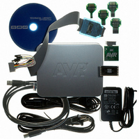
ATAVRONEKIT
Description
KIT AVR/AVR32 DEBUGGER/PROGRMMR
Manufacturer
Atmel
Series
AVR®r
Type
Debuggerr
Specifications of ATAVRONEKIT
Contents
Programmer/Debugger
Processor To Be Evaluated
AVR32
Data Bus Width
32 bit
Interface Type
ISP, JTAG
Core Architecture
AVR
Kit Contents
ATAVRONEKIT
Tool / Board Applications
General Purpose MCU, MPU, DSP, DSC
Development Tool Type
Hardware / Software - Dev Kit (Dev Tool)
Rohs Compliant
Yes
Mcu Supported Families
AVR32 32-bit MCU
For Use With/related Products
AVR® Devices
Lead Free Status / RoHS Status
Lead free / RoHS Compliant
Available stocks
Company
Part Number
Manufacturer
Quantity
Price
Company:

Part Number:
ATAVRONEKIT
Manufacturer:
Atmel
Quantity:
135


11. Power Management and Sleep Modes
11.1
11.2
11.3
11.3.1
11.3.2
11.3.3
11.3.4
11.3.5
8067M–AVR–09/10
Features
Overview
Sleep Modes
Idle Mode
Power-down Mode
Power-save Mode
Standby Mode
Extended Standby Mode
•
•
The XMEGA A1 provides various sleep modes tailored to reduce power consumption to a mini-
mum. All sleep modes are available and can be entered from Active mode. In Active mode the
CPU is executing application code. The application code decides when and what sleep mode to
enter. Interrupts from enabled peripherals and all enabled reset sources can restore the micro-
controller from sleep to Active mode.
In addition, Power Reduction registers provide a method to stop the clock to individual peripher-
als from software. When this is done, the current state of the peripheral is frozen and there is no
power consumption from that peripheral. This reduces the power consumption in Active mode
and Idle sleep mode.
In Idle mode the CPU and Non-Volatile Memory are stopped, but all peripherals including the
Interrupt Controller, Event System and DMA Controller are kept running. Interrupt requests from
all enabled interrupts will wake the device.
In Power-down mode all system clock sources, and the asynchronous Real Time Counter (RTC)
clock source, are stopped. This allows operation of asynchronous modules only. The only inter-
rupts that can wake up the MCU are the Two Wire Interface address match interrupts, and
asynchronous port interrupts, e.g pin change.
Power-save mode is identical to Power-down, with one exception: If the RTC is enabled, it will
keep running during sleep and the device can also wake up from RTC interrupts.
Standby mode is identical to Power-down with the exception that all enabled system clock
sources are kept running, while the CPU, Peripheral and RTC clocks are stopped. This reduces
the wake-up time when external crystals or resonators are used.
Extended Standby mode is identical to Power-save mode with the exception that all enabled
system clock sources are kept running while the CPU and Peripheral clocks are stopped. This
reduces the wake-up time when external crystals or resonators are used.
5 sleep modes
Power Reduction registers to disable clocks to unused peripherals
– Idle
– Power-down
– Power-save
– Standby
– Extended standby
XMEGA A1
22
Related parts for ATAVRONEKIT
Image
Part Number
Description
Manufacturer
Datasheet
Request
R

Part Number:
Description:
DEV KIT FOR AVR/AVR32
Manufacturer:
Atmel
Datasheet:

Part Number:
Description:
INTERVAL AND WIPE/WASH WIPER CONTROL IC WITH DELAY
Manufacturer:
ATMEL Corporation
Datasheet:
Part Number:
Description:
Low-Voltage Voice-Switched IC for Hands-Free Operation
Manufacturer:
ATMEL Corporation
Datasheet:
Part Number:
Description:
MONOLITHIC INTEGRATED FEATUREPHONE CIRCUIT
Manufacturer:
ATMEL Corporation
Datasheet:
Part Number:
Description:
AM-FM Receiver IC U4255BM-M
Manufacturer:
ATMEL Corporation
Datasheet:
Part Number:
Description:
Monolithic Integrated Feature Phone Circuit
Manufacturer:
ATMEL Corporation
Datasheet:
Part Number:
Description:
Multistandard Video-IF and Quasi Parallel Sound Processing
Manufacturer:
ATMEL Corporation
Datasheet:
Part Number:
Description:
High-performance EE PLD
Manufacturer:
ATMEL Corporation
Datasheet:
Part Number:
Description:
8-bit Flash Microcontroller
Manufacturer:
ATMEL Corporation
Datasheet:
Part Number:
Description:
2-Wire Serial EEPROM
Manufacturer:
ATMEL Corporation
Datasheet: