ATAVRONEKIT Atmel, ATAVRONEKIT Datasheet - Page 3
ATAVRONEKIT
Manufacturer Part Number
ATAVRONEKIT
Description
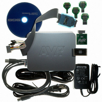
KIT AVR/AVR32 DEBUGGER/PROGRMMR
Manufacturer
Atmel
Series
AVR®r
Type
Debuggerr
Specifications of ATAVRONEKIT
Contents
Programmer/Debugger
Processor To Be Evaluated
AVR32
Data Bus Width
32 bit
Interface Type
ISP, JTAG
Core Architecture
AVR
Kit Contents
ATAVRONEKIT
Tool / Board Applications
General Purpose MCU, MPU, DSP, DSC
Development Tool Type
Hardware / Software - Dev Kit (Dev Tool)
Rohs Compliant
Yes
Mcu Supported Families
AVR32 32-bit MCU
For Use With/related Products
AVR® Devices
Lead Free Status / RoHS Status
Lead free / RoHS Compliant
Available stocks
Company
Part Number
Manufacturer
Quantity
Price
Company:

Part Number:
ATAVRONEKIT
Manufacturer:
Atmel
Quantity:
135


2. Pinout/Block Diagram
Figure 2-1.
Notes:
8067M–AVR–09/10
INDEX CORNER
1. For full details on pinout and pin functions refer to
2. VCC/GND on pin 83/84 are swapped compared to other VCC/GND to allow easier routing of GND to 32 kHz crystal.
Block diagram and pinout
AVCC
GND
GND
GND
VCC
VCC
PD0
PC0
PC1
PC2
PC3
PC4
PC5
PC6
PC7
PA6
PA7
PB0
PB1
PB2
PB3
PB4
PB5
PB6
PB7
1
2
3
4
5
6
7
8
9
10
11
12
13
14
15
16
17
18
19
20
21
22
23
24
25
ADC A
DAC A
ADC B
DAC B
AC A0
AC A1
AC B0
AC B1
Port C
Watchdog
OSC/CLK
Port R
Contro l
Contro l
Contro l
Power
Reset
“Pinout and Pin Functions” on page
Port D
EVENT ROUTING NETWORK
Port Q
TEMP
BOD
Interrupt Controlle r
Event System ctrl
DMA
CPU
DATA BU S
DATA BU S
Port E
VREF
RTC
E
FLASH
2
RAM
PROM
POR
OCD
Port F
49.
Port K
Port H
Port J
XMEGA A1
75
74
73
72
71
70
69
68
67
66
65
64
63
62
61
60
59
58
57
56
55
54
53
52
51
PK0
VCC
GND
PJ7
PJ6
PJ5
PJ4
PJ3
PJ2
PJ1
PJ0
VCC
GND
PH7
PH6
PH5
PH4
PH3
PH2
PH1
PH0
VCC
GND
PF7
PF6
3
Related parts for ATAVRONEKIT
Image
Part Number
Description
Manufacturer
Datasheet
Request
R

Part Number:
Description:
DEV KIT FOR AVR/AVR32
Manufacturer:
Atmel
Datasheet:

Part Number:
Description:
INTERVAL AND WIPE/WASH WIPER CONTROL IC WITH DELAY
Manufacturer:
ATMEL Corporation
Datasheet:
Part Number:
Description:
Low-Voltage Voice-Switched IC for Hands-Free Operation
Manufacturer:
ATMEL Corporation
Datasheet:
Part Number:
Description:
MONOLITHIC INTEGRATED FEATUREPHONE CIRCUIT
Manufacturer:
ATMEL Corporation
Datasheet:
Part Number:
Description:
AM-FM Receiver IC U4255BM-M
Manufacturer:
ATMEL Corporation
Datasheet:
Part Number:
Description:
Monolithic Integrated Feature Phone Circuit
Manufacturer:
ATMEL Corporation
Datasheet:
Part Number:
Description:
Multistandard Video-IF and Quasi Parallel Sound Processing
Manufacturer:
ATMEL Corporation
Datasheet:
Part Number:
Description:
High-performance EE PLD
Manufacturer:
ATMEL Corporation
Datasheet:
Part Number:
Description:
8-bit Flash Microcontroller
Manufacturer:
ATMEL Corporation
Datasheet:
Part Number:
Description:
2-Wire Serial EEPROM
Manufacturer:
ATMEL Corporation
Datasheet: