ATAVRONEKIT Atmel, ATAVRONEKIT Datasheet - Page 33
ATAVRONEKIT
Manufacturer Part Number
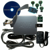
ATAVRONEKIT
Description
KIT AVR/AVR32 DEBUGGER/PROGRMMR
Manufacturer
Atmel
Series
AVR®r
Type
Debuggerr
Specifications of ATAVRONEKIT
Contents
Programmer/Debugger
Processor To Be Evaluated
AVR32
Data Bus Width
32 bit
Interface Type
ISP, JTAG
Core Architecture
AVR
Kit Contents
ATAVRONEKIT
Tool / Board Applications
General Purpose MCU, MPU, DSP, DSC
Development Tool Type
Hardware / Software - Dev Kit (Dev Tool)
Rohs Compliant
Yes
Mcu Supported Families
AVR32 32-bit MCU
For Use With/related Products
AVR® Devices
Lead Free Status / RoHS Status
Lead free / RoHS Compliant
Available stocks
Company
Part Number
Manufacturer
Quantity
Price
Company:

Part Number:
ATAVRONEKIT
Manufacturer:
Atmel
Quantity:
135


16. AWEX - Advanced Waveform Extension
16.1
16.2
8067M–AVR–09/10
Features
Overview
•
•
•
•
•
•
•
•
The Advanced Waveform Extension (AWEX) provides extra features to the Timer/Counter in
Waveform Generation (WG) modes. The AWEX enables easy and safe implementation of for
example, advanced motor control (AC, BLDC, SR, and Stepper) and power control applications.
Any WG output from a Timer/Counter 0 is split into a complimentary pair of outputs when any
AWEX feature is enabled. These output pairs go through a Dead-Time Insertion (DTI) unit that
enables generation of the non-inverted Low Side (LS) and inverted High Side (HS) of the WG
output with dead time insertion between LS and HS switching. The DTI output will override the
normal port value according to the port override setting. Optionally the final output can be
inverted by using the invert I/O setting for the port pin.
The Pattern Generation unit can be used to generate a synchronized bit pattern on the port it is
connected to. In addition, the waveform generator output from Compare Channel A can be dis-
tributed to, and override all port pins. When the Pattern Generator unit is enabled, the DTI unit is
bypassed.
The Fault Protection unit is connected to the Event System. This enables any event to trigger a
fault condition that will disable the AWEX output. Several event channels can be used to trigger
fault on several different conditions.
The AWEX is available for TCC0 and TCE0. The notation of these peripherals are AWEXC and
AWEXE.
Output with complementary output from each Capture channel
Four Dead Time Insertion (DTI) Units, one for each Capture channel
8-bit DTI Resolution
Separate High and Low Side Dead-Time Setting
Double Buffered Dead-Time
Event Controlled Fault Protection
Single Channel Multiple Output Operation (for BLDC motor control)
Double Buffered Pattern Generation
XMEGA A1
33
Related parts for ATAVRONEKIT
Image
Part Number
Description
Manufacturer
Datasheet
Request
R

Part Number:
Description:
DEV KIT FOR AVR/AVR32
Manufacturer:
Atmel
Datasheet:

Part Number:
Description:
INTERVAL AND WIPE/WASH WIPER CONTROL IC WITH DELAY
Manufacturer:
ATMEL Corporation
Datasheet:
Part Number:
Description:
Low-Voltage Voice-Switched IC for Hands-Free Operation
Manufacturer:
ATMEL Corporation
Datasheet:
Part Number:
Description:
MONOLITHIC INTEGRATED FEATUREPHONE CIRCUIT
Manufacturer:
ATMEL Corporation
Datasheet:
Part Number:
Description:
AM-FM Receiver IC U4255BM-M
Manufacturer:
ATMEL Corporation
Datasheet:
Part Number:
Description:
Monolithic Integrated Feature Phone Circuit
Manufacturer:
ATMEL Corporation
Datasheet:
Part Number:
Description:
Multistandard Video-IF and Quasi Parallel Sound Processing
Manufacturer:
ATMEL Corporation
Datasheet:
Part Number:
Description:
High-performance EE PLD
Manufacturer:
ATMEL Corporation
Datasheet:
Part Number:
Description:
8-bit Flash Microcontroller
Manufacturer:
ATMEL Corporation
Datasheet:
Part Number:
Description:
2-Wire Serial EEPROM
Manufacturer:
ATMEL Corporation
Datasheet: