ATAVRONEKIT Atmel, ATAVRONEKIT Datasheet - Page 90
ATAVRONEKIT
Manufacturer Part Number
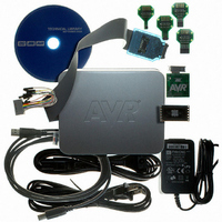
ATAVRONEKIT
Description
KIT AVR/AVR32 DEBUGGER/PROGRMMR
Manufacturer
Atmel
Series
AVR®r
Type
Debuggerr
Specifications of ATAVRONEKIT
Contents
Programmer/Debugger
Processor To Be Evaluated
AVR32
Data Bus Width
32 bit
Interface Type
ISP, JTAG
Core Architecture
AVR
Kit Contents
ATAVRONEKIT
Tool / Board Applications
General Purpose MCU, MPU, DSP, DSC
Development Tool Type
Hardware / Software - Dev Kit (Dev Tool)
Rohs Compliant
Yes
Mcu Supported Families
AVR32 32-bit MCU
For Use With/related Products
AVR® Devices
Lead Free Status / RoHS Status
Lead free / RoHS Compliant
Available stocks
Company
Part Number
Manufacturer
Quantity
Price
Company:

Part Number:
ATAVRONEKIT
Manufacturer:
Atmel
Quantity:
135


35. Errata
35.1
8067M–AVR–09/10
ATxmega128A1 rev. H
•
•
•
•
•
•
•
•
•
•
•
•
•
•
•
•
•
•
•
•
•
•
•
•
•
•
•
•
•
•
•
•
•
•
•
•
•
•
•
•
•
•
Bandgap voltage input for the ACs can not be changed when used for both ACs simultaneously
VCC voltage scaler for AC is non-linear
The ADC has up to ±2 LSB inaccuracy
ADC gain stage output range is limited to 2.4 V
Sampling speed limited to 500 ksps for supply voltage below 2.0V
ADC Event on compare match non-functional
Bandgap measurement with the ADC is non-functional when VCC is below 2.7V
Accuracy lost on first three samples after switching input to ADC gain stage
The input difference between two succeeding ADC samples is limited by VREF
Increased noise when using internal 1.0V reference at low temperature
Configuration of PGM and CWCM not as described in XMEGA A Manual
PWM is not restarted properly after a fault in cycle-by-cycle mode
BOD will be enabled at any reset
BODACT fuse location is not correct
Sampled BOD in Active mode will cause noise when bandgap is used as reference
DAC has up to ±10 LSB noise in Sampled Mode
DAC is nonlinear and inaccurate when reference is above 2.4V or VCC - 0.6V
DAC refresh may be blocked in S/H mode
Conversion lost on DAC channel B in event triggered mode
Both DFLLs and both oscillators have to be enabled for one to work
Access error when multiple bus masters are accessing SDRAM
EEPROM page buffer always written when NVM DATA0 is written
Pending full asynchronous pin change interrupts will not wake the device
Pin configuration does not affect Analog Comparator Output
Low level interrupt triggered when pin input is disabled
JTAG enable does not override Analog Comparator B output
NMI Flag for Crystal Oscillator Failure automatically cleared
Flash Power Reduction Mode can not be enabled when entering sleep
Some NVM Commands are non-functional
Crystal start-up time required after power-save even if crystal is source for RTC
Setting PRHIRES bit makes PWM output unavailable
Accessing EBI address space with PREBI set will lock Bus Master
RTC Counter value not correctly read after sleep
Pending asynchronous RTC-interrupts will not wake up device
TWI, the minimum I2C SCL low time could be violated in Master Read mode
TWI address-mask feature is non-functional
TWI, a general address call will match independent of the R/W-bit value
TWI Transmit collision flag not cleared on repeated start
Clearing TWI Stop Interrupt Flag may lock the bus
TWI START condition at bus timeout will cause transaction to be dropped
TWI Data Interrupt Flag erroneously read as set
WDR instruction inside closed window will not issue reset
XMEGA A1
90
Related parts for ATAVRONEKIT
Image
Part Number
Description
Manufacturer
Datasheet
Request
R

Part Number:
Description:
DEV KIT FOR AVR/AVR32
Manufacturer:
Atmel
Datasheet:

Part Number:
Description:
INTERVAL AND WIPE/WASH WIPER CONTROL IC WITH DELAY
Manufacturer:
ATMEL Corporation
Datasheet:
Part Number:
Description:
Low-Voltage Voice-Switched IC for Hands-Free Operation
Manufacturer:
ATMEL Corporation
Datasheet:
Part Number:
Description:
MONOLITHIC INTEGRATED FEATUREPHONE CIRCUIT
Manufacturer:
ATMEL Corporation
Datasheet:
Part Number:
Description:
AM-FM Receiver IC U4255BM-M
Manufacturer:
ATMEL Corporation
Datasheet:
Part Number:
Description:
Monolithic Integrated Feature Phone Circuit
Manufacturer:
ATMEL Corporation
Datasheet:
Part Number:
Description:
Multistandard Video-IF and Quasi Parallel Sound Processing
Manufacturer:
ATMEL Corporation
Datasheet:
Part Number:
Description:
High-performance EE PLD
Manufacturer:
ATMEL Corporation
Datasheet:
Part Number:
Description:
8-bit Flash Microcontroller
Manufacturer:
ATMEL Corporation
Datasheet:
Part Number:
Description:
2-Wire Serial EEPROM
Manufacturer:
ATMEL Corporation
Datasheet: