EPSILON5(SAM7) Equinox Technologies, EPSILON5(SAM7) Datasheet
EPSILON5(SAM7)
Specifications of EPSILON5(SAM7)


Related parts for EPSILON5(SAM7)


EPSILON5(SAM7) Summary of contents
Page 1
Portable ISP Programmer for Atmel, Atmel Wireless (Temic) and Philips FLASH Microcontrollers User Guide ...
Page 2
Contents Copyright Information ............................................................................................................iii Equinox Warranty Information ..............................................................................................iv Electromagnetic Compatibility (EMC) Compliance.............................................................vi RoHS Compliance...................................................................................................................vi Technical Support..................................................................................................................vii Product Documentation .......................................................................................................viii 1.0 Programmer Overview ......................................................................................................1 1.1 System Contents ............................................................................................................1 1.2 Hardware Overview (external layout) .............................................................................2 1.3 Hardware Overview (internal layout) ..............................................................................3 1.4 ...
Page 3
Programmer / Target System Power Supply Scenarios + Standalone Mode Programming Instructions ....................................................................................................37 3.1 Overview .......................................................................................................................37 3.2 Programmer / Target System Power Supply Schematic ..............................................38 3.3 Earthing requirements...................................................................................................40 3.3.1 Overview...............................................................................................................40 3.3.2 Laptop earthing issues .........................................................................................40 3.3.3 Desktop PC earthing ...
Page 4
... The purchaser may make one copy of the software for backup purposes. No part of this manual may be reproduced or transmitted in any form or by any means, electronic, mechanical, including photocopying, recording, or information retrieval systems, for any purpose other than for the purchaser’s personal use, without written permission. © 2000 - 2007 Copyright Equinox Technologies UK Limited. All rights reserved Atmel ...
Page 5
... Equinox Warranty Information This product is guaranteed by Equinox Technologies UK Limited for a period of 12 months (1 year) after the date of purchase against defects due to faulty workmanship or materials. One guarantee covers both parts and labour. Service under the guarantee is only provided upon presentation of reasonable evidence that the date of the claim is within the guarantee period (e.g. completed registration/guarantee card or a purchase receipt) ...
Page 6
... Equinox Technologies UK Ltd. cannot be held responsible for any programming problems which are ‘out of our control’. This type of problem is usually listed in the ‘Errata Sheet’ for the particular device being programmed and is available from the silicon vendor. Information contained in this manual is for guidance purposes only and is subject to change. E& ...
Page 7
Electromagnetic Compatibility (EMC) Compliance The ‘EPSILON5’ Approved Product designed for use in an ESD controlled environment i.e. development or production. This means, therefore, that the user must ensure that there is no possibility of damage ...
Page 8
Technical Support It is often the case that users experience problems when installing or using a product for the first time. If you have a technical support problem, please consult the following list for help: Manual On-line help Press <F1> ...
Page 9
Product Documentation This manual provides an overview of the contents of the EPSILON5 Programming System plus associated hardware and software. References may be made to other hardware and software products which are not covered in detail in this manual. Please ...
Page 10
ISP Pro – Manual This software is used to control the programmer in a production environment not supplied as standard with this programmer. The following sources of documentation are available for this software: • • • Labview – ...
Page 11
Downloading up-to-date documentation and software: In line with our policy of continuous improvement, the software and associated documentation for this product are updated on a regular basis. Please refer to the ‘Downloads Page’ for this product on our website at ...
Page 12
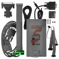
Programmer Overview 1.1 System Contents EPSILON5 MKII Programmer - User Guide V1.12 – 1 Hardware • EPSILON5 MKII Programmer • Jumper Links for internal jumpers Cables • DC Power Cable • 9-way Female to 9-way Male Serial ...
Page 13
Hardware Overview (external layout) 2 Top Panel ISP Cable Slot ISP cable plugs into relevant ISP Header internally and then exits the case through this slot. Front Panel <Target Vcc> LED - Indicates when ‘Target Vcc (Power)’ ...
Page 14
Hardware Overview (internal layout) EPSILON5 MKII Programmer - User Guide V1.12 – 1 Hardware 1. Atmel 6-way ISP (SPI) Header 2. Equinox 10-way ISP (SPI / UART) Header 3. Atmel 10-way ISP (SPI) Header 4. Jumper (J9) – Vcc ...
Page 15
Push Button Functions Button 4 The EPSILON5 programmer features two push buttons, <YES> and <NO>, which are used to control the programmer when it is operating in ‘Standalone Mode’. The function of these buttons is described below. Function of ...
Page 16
Programmer Specifications 1.5.1 Programmer Specifications Overview The table below details the hardware specifications for the programmer. Please refer to the stated section for further information about any specific parameter. # Parameter Description / comment 1 Target Device See Device ...
Page 17
PC Control Software The programmer can be controlled using: • • • • • • requirements PC running Windows 2000 NT4 / XP 11 Power Supply There are 3 possible ...
Page 18
ISP Headers 4 x ISP Headers (inside enclosure) i. ii. iii. iv. 20 Frequency generator Programmer can output a configurable square wave frequency output (SCK2) on the SCK2 pin. This is used to clock the Target Device in the ...
Page 19
Voltage range The programmer is designed to operate from a supply voltage in the range defined in the table below. Correct operation outside of these limits is not guaranteed. The programmer supply voltage can be derived from either the ...
Page 20
Current Consumption / Parameters 1.5.3.1 Current Consumption The programmer can either be powered from the Target System via one of the ISP Headers or from an independent power supply via CON1. The table below details the programmer current consumption ...
Page 21
Fig. 1.5.3.2 Programmer – maximum current ratings # Programmer mode 1 Programmer supplying power to the Target System 1.5.4 DC Power Input Connector (CON1 possible to power the programmer from an external power supply by plugging the DC ...
Page 22
J5 – RS-232 Communications Port & Serial Cables 1.5.6.1 Connecting the programmer to the PC COM port The EPSILON5 programmer communicates with a PC via the RS-232 Communications Port (J5). A suitable 9-way to 9-way serial cable is supplied ...
Page 23
Serial Cable Pin-outs Fig. 1.5.6.1 Pin-out RS-232 Communications Port Pin No. RS232 pin Description 1 DCD Not Connected 2 RXD Receive 3 TXD Transmit 4 DTR Not Connected 5 0 Volt 0V 6 DSR Not Connected ...
Page 24
EPSILON5 MKII Programmer - User Guide V1.12 – August 2007 13 ...
Page 25
Device Support 1.6.1 Devices supported by the programmer The programmer supports the following devices: # Silicon Family vendor 1 Atmel AT89S 2 Atmel AT90S (AVR) 3 Atmel AT90CAN 4 Atmel AT90CAN 5 Atmel AT90USB 6 Atmel AT90USB 7 Atmel ...
Page 26
Key: S – Device supported as standard U – Chargeable license upgrade required * – Device support not available at the time of this document going to press. Please contact Equinox for a device support update. 1.6.2 Programming Interface to ...
Page 27
EPSILON5 MKII Programmer - User Guide V1.12 – August 2007 ...
Page 28
Getting Started Guide EPSILON5 MKII Programmer - User Guide V1.12 – August 2007 17 ...
Page 29
Overview This section gives a ‘Quick Start’ Guide to using the programmer. Please refer to the table below for help installing the programmer hardware and software and also instructions on how to actually use the programmer. # Description 1 ...
Page 30
Hardware Installation Procedure Please follow the instructions below to set up the programmer hardware: # Action 1 Remove programmer from all packaging 2 Ensure you are wearing an ESD strap and/or you are working in an ESD protected environment. ...
Page 31
Select the required ISP Header and then plug the ISP Cable into this Header. Please refer to section 4. 8 Apply power to the programmer Connect 3.0-5.0V to CON1 via supplied lead (white stripe is +ve) or Fit J9 ...
Page 32
Switch PC power ON 16 Switch Programmer / Target System power ON 17 Hardware installation is now complete. Electrostatic Discharge (ESD) Warning! There are a number of electrostatic issues which must be taken into account to avoid damage to ...
Page 33
Software Overview and Installation 2.3.1 Software Overview The Epsilon programmer is supplied with a comprehensive Integrated Development Environment (IDE) called ‘EQTools Version 2.xx Software Suite’. This software supports creation and testing of so-called Programming Projects which can then be ...
Page 34
Programmer Control Mechanisms The programmer can be controlled from EQTools, from a Remote System and via the Equinox ISP- PRO software. An overview of the various control mechanisms is given below. Standalone Operation (Keypad) This indicates that the programmer ...
Page 35
Software Installation The Epsilon5 programmer comes with the software suite called EQTools as standard. The latest version of this software which was available at the time of shipping is supplied on CD-ROM with the programmer. However, this software version ...
Page 36
Operating the programmer The EPSILON5 programmer can be used in the following Operating Modes as detailed in the table below: # Programmer Connect Control Method Mode Software COM Port 1 Development Yes EQTools - EDS Mode ...
Page 37
ASCII Control Yes ASCII Text Mode Communications 26 Upgrade In this mode, the programmer Required is controlled via a simple ASCII Protocol. A simple Terminal Emulator is required to test out this mode or the ASCII commands can be ...
Page 38
Development Mode (EDS) 2.5.1 Overview In ‘Development Mode’, the programmer is controlled from the EQTools – EDS (Equinox Development Suite) running on a PC. The Development utility is called Equinox Development Suite or EDS for short. In this mode ...
Page 39
At the end of the EDS Wizard: Click the <Test> button Save the EDS file with an appropriate name eg. ATmega163.eds The EDS Window will now launch – see section 2.5.4 2.5.3 Testing an existing Programming Project in a ...
Page 40
Overview of EDS – Development Mode The EDS Utility consists of a series of tabs. Each tab controls a different area of functionality including FLASH Area Programming, EEPROM Area programming, Configuration Fuse Programming and Security Fuse programming ...
Page 41
Fig. 2.5.4.2 FLASH / EEPROM tab – functional description # 1 File name and This specifies the ‘File Name / path’ and ‘Last updated’ date of the file to be properties loaded into the Buffer Window. • • 2 Re-load ...
Page 42
Buffer Window - Control Buttons The Buffer Window within EDS is used as a virtual data store which allows data to be transferred from file Buffer Window Target Device and vice-versa. The ‘Buffer – Control Buttons’ support operations on ...
Page 43
Example of using EDS Here is an example of how to use EDS: • Select the <FLASH> tab • Click the <Load> button to load a file • Click the <Check Sig> button to check the Device Signature of ...
Page 44
Standalone Mode 2.6.1 Overview In ‘Standalone Mode’, the programmer is not connected to the PC and is controlled via the <YES> and <NO> push buttons on the front panel instead. This is ideal for both field and production ISP ...
Page 45
Executing a Programming Project in Standalone Mode # Action 1 Connect the programmer to a spare PC COM port 2 Apply power to the Programmer / Target System See section 3 for Power Supply scenarios 3 Upload your ‘Programming ...
Page 46
Script Mode ‘Script Mode’ is designed for production users who require logging of all programmer operations to a database. This mode utilises the Equinox ISP-PRO software which allows execution of Programming Scripts possible to write scripts to ...
Page 47
EPSILON5 MKII Programmer - User Guide V1.12 – August 2007 ...
Page 48
Programmer / Target System Power Supply Scenarios + Standalone Mode Programming Instructions 3.1 Overview The EPSILON5 programmer has been designed so that it can be powered both directly from a Target System (3.1 – 5.0V) and also from an ...
Page 49
Programmer / Target System Power Supply Schematic The schematic shown in fig. 3.2.2 details the possible power supply scenarios for powering both the programmer and the Target System. The key points to note are as follows: • The programmer ...
Page 50
Fig 3.2.2 – Programmer / Target System Power Supply Overview Schematic Please refer to fig 3.2.1 for an explanation of all circuit diagram labels etc. EPSILON5 MKII Programmer - User Guide V1.12 – August 2007 39 ...
Page 51
Earthing requirements 3.3.1 Overview When setting up the programmer to In-System Program (ISP) a device on a Target System, extreme care must be taken to ensure that the 0V of the PC, programmer, Target System and any external devices ...
Page 52
Earthing recommendations To avoid catastrophic damage to PC, programmer or target system: • Ensure that both your target system and PC are connected to a common earth point • Make sure that all interconnections are made before applying power ...
Page 53
Programmer Powers the Target System 3.4.1 Overview In this scenario, the programmer is constantly powered from an external power supply (not supplied) via the connector CON1. The Jumper J9 is fitted which connects the voltage applied to CON1 to ...
Page 54
Circuit Schematic - Programmer powers the Target System Please refer to fig 3.2.1 for an explanation of all circuit diagram labels etc. EPSILON5 MKII Programmer - User Guide V1.12 – August 2007 43 ...
Page 55
Set up instructions - Programmer powers the Target System The instructions below detail how to set up the programmer / Target System so that the programmer provides power to the Target System. Status LED key: # Action 1 Remove ...
Page 56
Replace programmer lid and tighten screws EPSILON5 MKII Programmer - User Guide V1.12 – August 2007 45 ...
Page 57
Programming Instructions (Standalone Mode) - Programmer powers the Target System The instructions detailed in the table below demonstrate how to program a Target Device in ‘Standalone’ mode when the programmer is powering the Target System assumed that ...
Page 58
Programming operation has FAILED ! 6b. To clear the ERROR CONDITION: Press key once 6c. To re-program the same Target System Go to step 4. 6d. To program a new Target System after a FAILURE: i. Disconnect ISP Cable ...
Page 59
Target System powers the Programmer 3.5.1 Overview In this scenario, the programmer is powered from the Target System via the ISP cable. The Jumper J9 is fitted which connects the Target Vcc voltage (V_TVCC) to CON1 VIN. This powers ...
Page 60
Circuit Schematic - Target System powers the Programmer Please refer to fig 3.2.1 for an explanation of all circuit diagram labels etc. EPSILON5 MKII Programmer - User Guide V1.12 – August 2007 49 ...
Page 61
Setup instructions - Target System powers the Programmer The instructions below detail how to set up the programmer / Target System so that the Target System provides power to the programmer. Status LED key: # Action 1 Remove programmer ...
Page 62
Programming Instructions (Standalone Mode) - Target System powers the programmer The instructions detailed in the table below demonstrate how to program a Target Device in ‘Standalone’ mode when the Target System is powering the programmer assumed that ...
Page 63
Programming operation has FAILED ! 7b. To clear the ERROR CONDITION: Press key once 7c. To re-program the same Target System Go to step 5. 7d. To program a new Target System after a FAILURE step ...
Page 64
Programmer and Target System are independently powered 3.6.1 Overview In this scenario, the programmer is powered from a completely independent supply to the Target System. The Jumper J9 is NOT fitted which isolates the Target Vcc voltage (V_TVCC) from ...
Page 65
Circuit Schematic - Programmer and Target System independently powered Please refer to fig 3.2.1 for an explanation of all circuit diagram labels etc. 54 EPSILON5 MKII Programmer - User Guide V1.12 – August 2007 ...
Page 66
Set up instructions - Programmer and Target System independently powered The instructions below detail how to set up the programmer / Target System so that they are independently powered. Status LED key: # Action 1 Remove programmer cover and ...
Page 67
Replace programmer lid and tighten screws 3.6.5 Programming Instructions As the programmer is always powered ON, the programming instructions are exactly the same as for when the programmer powers the Target System except that jumper J9 must be removed. ...
Page 68
ISP Header Selection 4.1 Overview The EPSILON5 programmer caters for many different connection methods to a Target System by featuring FOUR possible ISP Header connectors. Each header provides the necessary signals to program the Target Device plus Vcc (power) ...
Page 69
ISP Header Selection Chart (by header) The FOUR ISP Headers featured on the EPSILON5 are detailed in the table below. Please refer to the section indicated in the ‘refer to section’ column for specific details of each header. # ...
Page 70
J8 Atmel 10-way JTAG Header Device support: Atmel ATmega32/128 + any new devices with JTAG port EPSILON5 MKII Programmer - User Guide V1.12 – 1 4.9 st August 2007 59 ...
Page 71
ISP Header Selection Chart (by Device) The table below details which header to choose for a specified device or device family. The information contained in this manual does NOT show the actual connections to the Target Microcontroller. Please refer ...
Page 72
J3 - Atmel 6-way ISP Header (SPI Interface) This connection method is suitable for interfacing the EPSILON5 programmer to a Target System which features the following: • Atmel 6-way IDC ISP Header • An Atmel device which features the ...
Page 73
PROG_RESET O 6 PROG_GND P Key O - Output from programmer to Target Device I - Input to programmer from Target Device P - Passive eg. GROUND and power rails N/C - Not connected 62 RESET Target RESET control ...
Page 74
J6(a) - Equinox 10-way Header (Generic SPI Interface) This connection method is suitable for interfacing the EPSILON5 programmer to a Target System which features the following: • Equinox 10-way IDC ISP Header • An Atmel device which features the ...
Page 75
PROG_TSCK2 O 4 PROG_MOSI PROG_MISO I 7 PROG_GND P 8 PROG_SCK1 O 9 PROG_GND P 10 PROG_RESET O 64 XTAL1 SCK2 Clock Output (*Optional*) This output signal can be used to Only connect this ...
Page 76
Key O - Output from programmer to Target Device I - Input to programmer from Target Device P - Passive eg. GROUND and power rails N/C - Not connected EPSILON5 MKII Programmer - User Guide V1.12 – August ...
Page 77
J6(b) - Equinox 10-way Header (ATtiny11/12/15 HV Interface) This connection method is suitable for interfacing the EPSILON5 programmer to a Target System which features the following: • Equinox 10-way IDC ISP Header • An Atmel ATtiny microcontroller eg. ATtiny11/12/15 ...
Page 78
N PROG_SII O 7 PROG_GND P 8 PROG_SDO I 9 PROG_GND P 10 PROG_RESET/VPP O Key O - Output from programmer to Target Device I - Input to programmer from Target Device P - Passive eg. GROUND ...
Page 79
J6(c) - Equinox 10-way Header (UART Boot Loader) This connection method is suitable for interfacing the EPSILON5 programmer to a Target System which features the following: • Equinox 10-way IDC ISP Header • An Atmel Wireless T89C51Rx2 / CC01 ...
Page 80
N PROG_RXD I 7 PROG_GND P 8 PROG_ACTIVE O 9 PROG_GND P 10 PROG_RESET O Key O - Output from programmer to Target Device I - Input to programmer from Target Device P - Passive eg. GROUND ...
Page 81
J7 - Atmel 10-way Header (SPI Interface) This connection method is suitable for interfacing the EPSILON5 programmer to a Target System which features the following: • Atmel 10-way IDC ISP Header • An Atmel device which features the 3-wire ...
Page 82
PROG_RESET O 6 PROG_GND P 7 PROG_SCK1 O 8 PROG_GND P 9 PROG_MISO I 10 PROG_GND P Key O - Output from programmer to Target Device I - Input to programmer from Target Device P - Passive eg. GROUND ...
Page 83
J8 - Atmel 10-way JTAG Header (JTAG Interface) This connection method is suitable for interfacing the EPSILON5 programmer to a Target System which features the following: • An Atmel device which features a JTAG ISP port e.g. ATmega128 / ...
Page 84
PROG_VCC PROG_TDI O 10 PROG_GND P Key O - Output from programmer to Target Device I - Input to programmer from Target Device P - Passive eg. GROUND and power rails N/C - Not ...
Page 85
ISP Cable considerations The programmer is supplied with a single 10-way ISP Cable as standard. This cable is terminated with a 10-way IDC 0.1” female polarised plug at each end. The cable is wired as a so-called ‘straigh- through’ ...