ATAVRSB100 Atmel, ATAVRSB100 Datasheet - Page 14
ATAVRSB100
Manufacturer Part Number
ATAVRSB100
Description
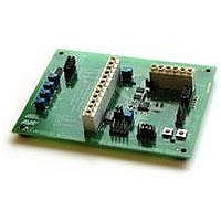
SMART BATTERY DEVELOPMENT KIT
Manufacturer
Atmel
Type
Smart Batteryr
Datasheet
1.ATAVRSB100.pdf
(20 pages)
Specifications of ATAVRSB100
Contents
Fully Assembled Evaluation Board
Processor
ATmega406
Processor To Be Evaluated
ATmega406
Data Bus Width
8 bit
Interface Type
JTAG
For Use With/related Products
ATmega406
Lead Free Status / RoHS Status
Contains lead / RoHS non-compliant
Other names
Q2367281


2.7.3 External Thermistors
14
AVR454
interrupt service routine. This approach also allows the use of a single current-limiting
resistor, as only one LED is enabled at a time.
Table 2-8. JB1: LED enable jumper block
JB2 provides access to several I/O signals as well as extra signals used in the
software implementation provided by Atmel (specifically the SMBCLK signal and the
SPARE pushbutton). Additionally, power for the LEDs can be selected here to come
either directly from 3.3V or from PB6 (OC0A PWM output).
Table 2-9. JB2: Miscellaneous signals jumper block
Using HDR1 (described in Table 2-10 below), SB100 provides control and
measurement for up to four external thermistors. PA0-3 are inputs to the VADC with a
range of 0 – 1.100V, while PA4 has a range of 0 – 5.500V. Thus, for best accuracy
and lowest power, one of the inputs PA0-3 should be used to read external
thermistors. Using the Vref output of 1.100V to power the thermistor circuitry ensures
that the maximum ADC range is available without concern for circuit tolerances, as
would be the case if 3.3V were used.
In practice, PA0 is shorted to the common bus - the odd-numbered pins of HDR1 -
while PA1-4 connect to individual thermistors. The other side of all thermistors ties to
the bus. The PAx VADC inputs have a relatively low input impedance of about 100K.
Pin
1
2
3
4
5
6
7
8
9
10
Pin
1
2
3
4
5
6
7
8
9
10
Name
LED1-K
PB4
LED2-K
PB5
LED3-K
PB7
LED4-K
PD0
LED5-K
PD1
Name
GND
PA5
SMBCLK
PA6
SW1
PA7
LED_PWR
PB6
LED_PWR
+3.3V
Direction
Output
Output
Output
Output
Output
Direction
I/O
I/O
Input
Output
Input
Output
Usage
Unused
Tied to PA6 for SMBus idle detection
Tied to SMBCLK for SMBus idle detection
Spare switch to activate Capacity Indicator LEDs
SW1 pushbutton input
Common positive feed to all LEDs
PWM to LEDs
Common positive feed to all LEDs
Steady supply to LEDs
Usage
LED1 enable, active-low
LED2 enable, active-low
LED3 enable, active-low
LED4 enable, active-low
LED5 enable, active-low
2598C-AVR-06/06
Related parts for ATAVRSB100
Image
Part Number
Description
Manufacturer
Datasheet
Request
R

Part Number:
Description:
DEV KIT FOR AVR/AVR32
Manufacturer:
Atmel
Datasheet:

Part Number:
Description:
INTERVAL AND WIPE/WASH WIPER CONTROL IC WITH DELAY
Manufacturer:
ATMEL Corporation
Datasheet:
Part Number:
Description:
Low-Voltage Voice-Switched IC for Hands-Free Operation
Manufacturer:
ATMEL Corporation
Datasheet:
Part Number:
Description:
MONOLITHIC INTEGRATED FEATUREPHONE CIRCUIT
Manufacturer:
ATMEL Corporation
Datasheet:
Part Number:
Description:
AM-FM Receiver IC U4255BM-M
Manufacturer:
ATMEL Corporation
Datasheet:
Part Number:
Description:
Monolithic Integrated Feature Phone Circuit
Manufacturer:
ATMEL Corporation
Datasheet:
Part Number:
Description:
Multistandard Video-IF and Quasi Parallel Sound Processing
Manufacturer:
ATMEL Corporation
Datasheet:
Part Number:
Description:
High-performance EE PLD
Manufacturer:
ATMEL Corporation
Datasheet:
Part Number:
Description:
8-bit Flash Microcontroller
Manufacturer:
ATMEL Corporation
Datasheet:
Part Number:
Description:
2-Wire Serial EEPROM
Manufacturer:
ATMEL Corporation
Datasheet: