EVAL-AD7490CB Analog Devices Inc, EVAL-AD7490CB Datasheet - Page 10
EVAL-AD7490CB
Manufacturer Part Number
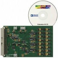
EVAL-AD7490CB
Description
BOARD EVAL FOR AD7490
Manufacturer
Analog Devices Inc
Datasheet
1.AD7490BRUZ.pdf
(28 pages)
Specifications of EVAL-AD7490CB
Number Of Adc's
1
Number Of Bits
12
Sampling Rate (per Second)
1M
Data Interface
Serial
Inputs Per Adc
16 Single Ended
Input Range
0 ~ 5 V
Power (typ) @ Conditions
12.5mW @ 1MSPS, 5 V
Voltage Supply Source
Single
Operating Temperature
-40°C ~ 85°C
Utilized Ic / Part
AD7490
Lead Free Status / RoHS Status
Contains lead / RoHS non-compliant


AD7490
TERMINOLOGY
Integral Nonlinearity
This is the maximum deviation from a straight line passing
through the endpoints of the ADC transfer function. The end-
points of the transfer function are zero scale, a point 1 LSB
below the first code transition, and full scale, a point 1 LSB
above the last code transition.
Differential Nonlinearity
This is the difference between the measured and the ideal 1 LSB
change between any two adjacent codes in the ADC.
Offset Error
This is the deviation of the first code transition (00 … 000) to
(00 … 001) from the ideal, that is, AGND + 1 LSB.
Offset Error Match
This is the difference in offset error between any two channels.
Gain Error
This is the deviation of the last code transition (111 … 110) to
(111 … 111) from the ideal (that is, REF
offset error has been adjusted out.
Gain Error Match
This is the difference in gain error between any two channels.
Zero Code Error
This applies when using the twos complement output coding
option, in particular to the 2 × REF
to +REF
midscale transition (all 0s to all 1s) from the ideal V
that is, REF
Zero Code Error Match
This is the difference in zero code error between any two
channels.
Positive Gain Error
This applies when using the twos complement output coding
option, in particular the 2 × REF
+REF
last code transition (011 … 110) to (011 … 111) from the ideal
(that is, +REF
adjusted out.
Positive Gain Error Match
This is the difference in positive gain error between any two
channels.
Negative Gain Error
This applies when using the twos complement output coding
option, in particular to the 2 × REF
to +REF
first code transition (100 … 000) to (100 … 001) from the ideal
(that is, −REF
adjusted out.
IN
biased about the REF
IN
IN
biased about the REF
biased about the REF
IN
− 1 LSB.
IN
IN
− 1 LSB) after the zero code error has been
+ 1 LSB) after the zero code error has been
IN
point. It is the deviation of the
IN
IN
IN
point. It is the deviation of the
point. It is the deviation of the
input range with −REF
IN
IN
input range with −REF
input range with −REF
IN
− 1 LSB) after the
IN
voltage,
IN
to
IN
IN
Rev. C | Page 10 of 28
Negative Gain Error Match
This is the difference in negative gain error between any two
channels.
Channel-to-Channel Isolation
Channel-to-channel isolation is a measure of the level of
crosstalk between channels. It is measured by applying a full-
scale 400 kHz sine wave signal to all 15 nonselected input
channels and determining how much that signal is attenuated in
the selected channel with a 50 kHz signal. This specification is
the worst case across all 16 channels for the AD7490.
PSR (Power Supply Rejection)
Variations in power supply affect the full scale transition, but
not the converter linearity. Power supply rejection is the
maximum change in the full-scale transition point due to a
change in power supply voltage from the nominal value. (see
the Typical Performance Characteristics section).
Track-and-Hold Acquisition Time
The track-and-hold amplifier returns into track on the 14
SCLK falling edge. Track-and-hold acquisition time is the
minimum time required for the track-and-hold amplifier to
remain in track mode for its output to reach and settle to within
±1 LSB of the applied input signal, given a step change to the
input signal.
Signal-to-(Noise + Distortion) Ratio
This is the measured ratio of signal to (noise + distortion) at the
output of the analog-to-digital converter. The signal is the rms
amplitude of the fundamental. Noise is the sum of all nonfunda-
mental signals up to half the sampling frequency (f
dc. The ratio is dependent on the number of quantization levels
in the digitization process; the more levels, the smaller the quan-
tization noise. The theoretical signal-to-(noise + distortion) ratio
for an ideal N-bit converter with a sine wave input is given by
Thus for a 12-bit converter, this is 74 dB.
Total Harmonic Distortion
Total harmonic distortion (THD) is the ratio of the rms sum of
harmonics to the fundamental. For the AD7490, it is defined as
where V
V
sixth harmonics.
4
, V
Signal-to-(Noise + Distortion) (dB) = 6.02 N + 1.76
THD
5
, and V
1
is the rms amplitude of the fundamental and V
( )
dB
6
are the rms amplitudes of the second through the
=
20
×
log
V
2
2
+
V
3
2
+
V
V
1
4
2
+
V
5
2
+
V
S
/2), excluding
6
2
2
, V
th
3
,
Related parts for EVAL-AD7490CB
Image
Part Number
Description
Manufacturer
Datasheet
Request
R

Part Number:
Description:
ENERCHIP CC EVAL KIT
Manufacturer:
Cymbet Corporation
Datasheet:

Part Number:
Description:
BOARD EVAL FOR AD976
Manufacturer:
Analog Devices Inc
Datasheet:

Part Number:
Description:
BOARD EVAL FOR ADXL345
Manufacturer:
Analog Devices Inc
Datasheet:

Part Number:
Description:
ENERCHIP CC SEH EVAL KIT
Manufacturer:
Cymbet Corporation
Datasheet:

Part Number:
Description:
ENERCHIP EP ENERGY HARVEST EVAL
Manufacturer:
Cymbet Corporation
Datasheet:

Part Number:
Description:
EVAL BOARD FOR TW6864-LB2-GR
Manufacturer:
Intersil
Datasheet:
Part Number:
Description:
EVAL BOARD FOR TW8816-LB3-GR
Manufacturer:
Intersil
Datasheet:
Part Number:
Description:
EVAL BOARD FOR TW8817-TA3-GRS
Manufacturer:
Intersil
Datasheet:

Part Number:
Description:
EVALUATION MODULE FOR ADUM4160
Manufacturer:
Analog Devices Inc
Datasheet:

Part Number:
Description:
BOARD EVALUATION ADCMP581BCP
Manufacturer:
Analog Devices Inc
Datasheet:
Part Number:
Description:
BOARD EVALUATION ADM1041
Manufacturer:
Analog Devices Inc
Datasheet:

Part Number:
Description:
EVAL BOARD FOR STM32F107VCT
Manufacturer:
STMicroelectronics
Datasheet:
Part Number:
Description:
BOARD EVAL FOR AD1954
Manufacturer:
Analog Devices Inc
Datasheet:
Part Number:
Description:
BOARD EVAL FOR AD1955
Manufacturer:
Analog Devices Inc
Datasheet:

Part Number:
Description:
BOARD EVAL FOR AD7655
Manufacturer:
Analog Devices Inc
Datasheet: