EVAL-AD7490CB Analog Devices Inc, EVAL-AD7490CB Datasheet - Page 20
EVAL-AD7490CB
Manufacturer Part Number
EVAL-AD7490CB
Description
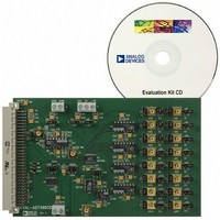
BOARD EVAL FOR AD7490
Manufacturer
Analog Devices Inc
Datasheet
1.AD7490BRUZ.pdf
(28 pages)
Specifications of EVAL-AD7490CB
Number Of Adc's
1
Number Of Bits
12
Sampling Rate (per Second)
1M
Data Interface
Serial
Inputs Per Adc
16 Single Ended
Input Range
0 ~ 5 V
Power (typ) @ Conditions
12.5mW @ 1MSPS, 5 V
Voltage Supply Source
Single
Operating Temperature
-40°C ~ 85°C
Utilized Ic / Part
AD7490
Lead Free Status / RoHS Status
Contains lead / RoHS non-compliant


AD7490
Auto Shutdown (PM1 = 0, PM0 = 1)
In this mode, the AD7490 automatically enters shutdown at the
end of each conversion when the control register is updated.
When the part is in shutdown, the track-and-hold is in hold
mode. Figure 24 shows the general diagram of the operation of
the AD7490 in this mode.
In shutdown mode, all internal circuitry on the AD7490 is
powered down. The part retains information in the control
register during shutdown. The AD7490 remains in shutdown
until the next CS falling edge it receives. On this CS falling edge,
the track-and-hold that was on hold while the part was in shut-
down mode returns to track-and-hold. Wake-up time from auto
shutdown is 1 μs, and the user should ensure that 1 μs elapses
before attempting a valid conversion. When running the AD7490
with a 20 MHz clock, one dummy cycle of 16 × SCLK should be
sufficient to ensure the part is fully powered up. During this
dummy cycle, the contents of the control register should remain
unchanged; therefore, the WRITE bit should be 0 on the DIN
line. This dummy cycle effectively halves the throughput rate of
the part, with every other conversion result being valid. In this
mode, the power consumption of the part is greatly reduced
with the part entering shutdown at the end of each conversion.
When the control register is programmed to move into auto
shutdown, it does so at the end of the conversion. The user can
move the ADC in and out of the low power state by controlling
the CS signal.
DOUT
DOUT
SCLK
SCLK
DIN
DIN
CS
CS
CONTROL REGISTER IS LOADED ON THE
FIRST 12 CLOCKS, PM1 = 0, PM0 = 1
CHANNE L IDENTIFIER BITS + CONVERSION RESULT
DATA IN TO CONTROL/SHADOW REGISTER
1
CHANNE L IDENTIFIER BITS + CONVERSION RESULT
CONTROL REGISTER IS LOADED ON THE
FIRST 12 CLOCKS, PM1 = 0, PM0 = 0
DATA IN TO CONTROL/SHADOW REGISTER
1
SHUTDOWN ON CS
RISING EDGE AS
PM1 = 0, PM0 = 1
STANDBY ON CS
RISING EDGE AS
12
PM1 = 0, PM0 = 0
PART ENTERS
PART ENTERS
16
16
PART BEGINS
TO POWER
UP ON CS
FALLING EDGE
PART BEGINS
TO POWER
UP ON CS
FALLING EDGE
Figure 24. Auto Shutdown Mode Operation
CONTROL REGISTER CONTENTS SHOULD
NOT CHANGE, WRITE BIT = 0
Figure 25. Auto Standby Mode Operation
1
CONTROL REGISTER CONTENTS SHOULD
REMAIN UNCHANGED, WRITE BIT = 0
1
Rev. C | Page 20 of 28
DUMMY CONVERSION
DUMMY CONVERSION
INVALID DATA
INVALID DATA
Auto Standby (PM1 = PM0 = 0)
In this mode, the AD7490 automatically enters standby mode at
the end of each conversion when the control register is updated.
Figure 25 shows the general diagram of the operation of the
AD7490 in this mode. When the part is in standby, portions of
the AD7490 are powered-down, but the on-chip bias generator
remains powered up. The part retains information in the control
register during standby. The AD7490 remains in standby until it
receives the next CS falling edge. On this CS falling edge, the
track-and-hold that was on hold while the part was in standby
returns to track. Wake-up time from standby is 1 μs; the user
should ensure that 1 μs elapses before attempting a valid conver-
sion on the part in this mode. When running the AD7490 with
a 20 MHz clock, one dummy cycle of 16 × SCLK should be
sufficient to ensure the part is fully powered up. During this
dummy cycle, the contents of the control register should remain
unchanged; therefore, the WRITE bit should be set to 0 on the
DIN line. This dummy cycle effectively halves the throughput
rate of the part with every other conversion result being valid.
In this mode, the power consumption of the part is greatly
reduced with the part entering standby at the end of each con-
version. When the control register is programmed to move into
auto standby, it does so at the end of the conversion. The user
can move the ADC in and out of the low power state by
controlling the CS signal.
12
16
16
PART IS FULLY
POWERED UP
PART IS FULLY
POWERED UP
TO KEEP PART IN THIS MODE, LOAD PM1 = 0, PM0 = 1
IN CONTROL REGISTER OR SET WRITE BIT = 0
TO KEEP PART IN THIS MODE, LOAD PM1 = 0,
PM0 = 0 IN CONTROL REGISTER
CHANNE L IDENTIFIER BITS + CONVERSION RESULT
DATA IN TO CONTROL/SHADOW REGISTER
DATA IN TO CONTROL/SHADOW REGISTER
1
CHANNE L IDENTIFIER BITS + CONVERSION RESULT
1
SHUTDOWN ON CS
12
RISING EDGE AS
STANDBY ON CS
RISING EDGE AS
PM1 = 0, PM0 = 1
PM1 = 0, PM0 = 0
PART ENTERS
PART ENTERS
16
1
6
Related parts for EVAL-AD7490CB
Image
Part Number
Description
Manufacturer
Datasheet
Request
R

Part Number:
Description:
ENERCHIP CC EVAL KIT
Manufacturer:
Cymbet Corporation
Datasheet:

Part Number:
Description:
BOARD EVAL FOR AD976
Manufacturer:
Analog Devices Inc
Datasheet:

Part Number:
Description:
BOARD EVAL FOR ADXL345
Manufacturer:
Analog Devices Inc
Datasheet:

Part Number:
Description:
ENERCHIP CC SEH EVAL KIT
Manufacturer:
Cymbet Corporation
Datasheet:

Part Number:
Description:
ENERCHIP EP ENERGY HARVEST EVAL
Manufacturer:
Cymbet Corporation
Datasheet:

Part Number:
Description:
EVAL BOARD FOR TW6864-LB2-GR
Manufacturer:
Intersil
Datasheet:
Part Number:
Description:
EVAL BOARD FOR TW8816-LB3-GR
Manufacturer:
Intersil
Datasheet:
Part Number:
Description:
EVAL BOARD FOR TW8817-TA3-GRS
Manufacturer:
Intersil
Datasheet:

Part Number:
Description:
EVALUATION MODULE FOR ADUM4160
Manufacturer:
Analog Devices Inc
Datasheet:

Part Number:
Description:
BOARD EVALUATION ADCMP581BCP
Manufacturer:
Analog Devices Inc
Datasheet:
Part Number:
Description:
BOARD EVALUATION ADM1041
Manufacturer:
Analog Devices Inc
Datasheet:

Part Number:
Description:
EVAL BOARD FOR STM32F107VCT
Manufacturer:
STMicroelectronics
Datasheet:
Part Number:
Description:
BOARD EVAL FOR AD1954
Manufacturer:
Analog Devices Inc
Datasheet:
Part Number:
Description:
BOARD EVAL FOR AD1955
Manufacturer:
Analog Devices Inc
Datasheet:

Part Number:
Description:
BOARD EVAL FOR AD7655
Manufacturer:
Analog Devices Inc
Datasheet: