EVAL-AD7490CB Analog Devices Inc, EVAL-AD7490CB Datasheet - Page 23
EVAL-AD7490CB
Manufacturer Part Number
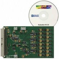
EVAL-AD7490CB
Description
BOARD EVAL FOR AD7490
Manufacturer
Analog Devices Inc
Datasheet
1.AD7490BRUZ.pdf
(28 pages)
Specifications of EVAL-AD7490CB
Number Of Adc's
1
Number Of Bits
12
Sampling Rate (per Second)
1M
Data Interface
Serial
Inputs Per Adc
16 Single Ended
Input Range
0 ~ 5 V
Power (typ) @ Conditions
12.5mW @ 1MSPS, 5 V
Voltage Supply Source
Single
Operating Temperature
-40°C ~ 85°C
Utilized Ic / Part
AD7490
Lead Free Status / RoHS Status
Contains lead / RoHS non-compliant


If the WEAK/ TRI bit in the control register is set to 1, instead of
returning to true three-state on the 16
DOUT line is pulled weakly to the logic level corresponding to
ADD3 of the next serial transfer. This is done to ensure that the
MSB of the next serial transfer is set up in time for the first
SCLK falling edge after the CS falling edge. If the WEAK/ TRI bit
is set to 0 and the DOUT line has been in true three-state
between conversions, the ADD3 address bit may not be set up
in time for the DSP/microcontroller to clock it in successfully,
depending on the particular DSP or microcontroller interfacing
to the AD7490. In this case, ADD3 would only be driven from
the falling edge of CS and must then be clocked in by the DSP
on the following falling edge of SCLK. However, if the WEAK/
TRI bit is set to 1, although DOUT is driven with the ADD3
address bit since the last conversion, it is nevertheless so weakly
driven that another device may still take control of the bus. It
does not lead to a bus contention (for example, a 10 kΩ pull-up
or pull-down resistor is sufficient to overdrive the logic level of
ADD3 between conversions), and all 16 channels may be
identified. If this does happen and another device takes control
of the bus, it is not guaranteed that DOUT will be fully driven
to ADD3 again in time for the read operation when control of
the bus is taken back.
This is especially useful if using an automatic sequence mode to
identify to which channel each result corresponds. If only the
first eight channels are in use, Address Bit ADD3 does not need
to be decoded, and whether it is successfully clocked in as a 1
or 0 does not matter as long as it is still counted by the DSP/
microcontroller as the MSB of the 16-bit serial transfer.
POWER vs. THROUGHPUT RATE
By operating the AD7490 in auto shutdown or auto standby
mode, the average power consumption of the ADC decreases at
lower throughput rates. Figure 29 shows that as the throughput
rate is reduced, the part remains in shutdown state longer and
the average power consumption drops accordingly over time.
For example, if the AD7490 is operated in a continuous
sampling mode with a throughput rate of 100 kSPS and an
SCLK of 20 MHz (V
is, the device is in auto shutdown mode), the power
consumption is calculated as shown in Equation 1.
The maximum power dissipation during normal operation is
12.5 mW (V
down is one dummy cycle, that is, 1 μs, and the remaining
conversion time is another cycle, that is, 1 μs, then the AD7490
can be said to dissipate 12.5 mW for 2 μs during each conver-
sion cycle. For the remainder of the conversion cycle, 8 μs, the
DD
= 5 V). If the power-up time from auto shut-
DD
= 5 V), with PM1 = 0 and PM0 = 1 (that
th
SCLK falling edge, the
Rev. C | Page 23 of 28
part remains in shutdown mode. The AD7490 can be said to
dissipate 2.5 μW for the remaining 8 μs of the conversion cycle.
If the throughput rate is 100 kSPS, the cycle time is 10 μs and
the average power dissipated during each cycle is
When operating the AD7490 in auto standby mode (PM1 =
PM0 = 0 at 5 V, 100 kSPS), the AD7490 power dissipation is
calculated as shown in Equation 2.
The maximum power dissipation is 12.5 mW at 5 V during nor-
mal operation. Again the power-up time from auto standby is
one dummy cycle, 1 μs, and the remaining conversion time is
another dummy cycle, 1 μs. The AD7490 dissipates 12.5 mW
for 2 μs during each conversion cycle. For the remainder of the
conversion cycle, 8 μs, the part remains in standby mode,
dissipating 460 μW for 8 μs. If the throughput rate is 100 kSPS,
the cycle time is 10 μs and the average power dissipated during
each conversion cycle is
Figure 29 shows the power vs. throughput rate when using both
the auto shutdown mode and auto standby mode with 5 V
supplies. At the lower throughput rates, power consumption for
the auto shutdown mode is lower than that for the auto standby
mode, with the AD7490 dissipating less power when in shut-
down compared to standby. As the throughput rate is increased,
however, the part spends less time in power-down states; hence,
the difference in power dissipated is negligible between modes.
For 3 V supplies, the power consumption of the AD7490
decreases. Similar power calculations can be done at 3 V.
10
10
2
2
0.01
0.1
10
×
×
1
Figure 29. Power vs. Throughput Rate in Auto Shutdown
0
12
12
V
AUTO STANDBY
DD
5 .
5 .
mW
= 5V
mW
50
+
+
10
10
8
8
100
and Auto Standby Mode
AUTO SHUTDOWN
×
×
THROUGHPUT (kSPS)
460
2
5 .
150
μW
μW
=
=
. 2
200
. 2
502
868
mW
mW
250
300
AD7490
350
(1)
(2)
Related parts for EVAL-AD7490CB
Image
Part Number
Description
Manufacturer
Datasheet
Request
R

Part Number:
Description:
ENERCHIP CC EVAL KIT
Manufacturer:
Cymbet Corporation
Datasheet:

Part Number:
Description:
BOARD EVAL FOR AD976
Manufacturer:
Analog Devices Inc
Datasheet:

Part Number:
Description:
BOARD EVAL FOR ADXL345
Manufacturer:
Analog Devices Inc
Datasheet:

Part Number:
Description:
ENERCHIP CC SEH EVAL KIT
Manufacturer:
Cymbet Corporation
Datasheet:

Part Number:
Description:
ENERCHIP EP ENERGY HARVEST EVAL
Manufacturer:
Cymbet Corporation
Datasheet:

Part Number:
Description:
EVAL BOARD FOR TW6864-LB2-GR
Manufacturer:
Intersil
Datasheet:
Part Number:
Description:
EVAL BOARD FOR TW8816-LB3-GR
Manufacturer:
Intersil
Datasheet:
Part Number:
Description:
EVAL BOARD FOR TW8817-TA3-GRS
Manufacturer:
Intersil
Datasheet:

Part Number:
Description:
EVALUATION MODULE FOR ADUM4160
Manufacturer:
Analog Devices Inc
Datasheet:

Part Number:
Description:
BOARD EVALUATION ADCMP581BCP
Manufacturer:
Analog Devices Inc
Datasheet:
Part Number:
Description:
BOARD EVALUATION ADM1041
Manufacturer:
Analog Devices Inc
Datasheet:

Part Number:
Description:
EVAL BOARD FOR STM32F107VCT
Manufacturer:
STMicroelectronics
Datasheet:
Part Number:
Description:
BOARD EVAL FOR AD1954
Manufacturer:
Analog Devices Inc
Datasheet:
Part Number:
Description:
BOARD EVAL FOR AD1955
Manufacturer:
Analog Devices Inc
Datasheet:

Part Number:
Description:
BOARD EVAL FOR AD7655
Manufacturer:
Analog Devices Inc
Datasheet: