AD9956/PCB Analog Devices Inc, AD9956/PCB Datasheet - Page 27
AD9956/PCB
Manufacturer Part Number
AD9956/PCB
Description
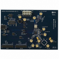
BOARD EVAL FOR AD9956
Manufacturer
Analog Devices Inc
Datasheet
1.AD9956YCPZ.pdf
(32 pages)
Specifications of AD9956/PCB
Module/board Type
Evaluation Board
For Use With/related Products
AD9956
Lead Free Status / RoHS Status
Contains lead / RoHS non-compliant


CONTROL FUNCTION REGISTER DESCRIPTIONS
Control Function Register 1 (CFR1)
This control register is comprised of four bytes, all of which
must be written during a write operation involving CFR1. CFR1
is used to control various functions, features, and operating
modes of the AD9956. The functionality of each bit(s) is
described below. In general, the bit is named for the function it
serves when the bit is set.
CFR1<31:25> Open. Unused locations. Write a Logic 0
CFR1<24> PLL Lock Error (Read-Only)
When the device is operating in automatic synchronization
mode or hardware manual synchronization mode (see below),
the PLL_LOCK/ SYNC_IN pin behaves as the SYNC_IN. To
determine whether or not the PLL has become unlocked while
in synchronization mode, this bit serves as a flag to indicate that
an unlocked condition has occurred within the phase frequency
detector. Once set, the flag stays high until it is cleared by a
readback of the value even though the loop might have
relocked. Readback of the CFR1 register clears this bit.
CFR1<24> = 0 indicates that the loop has maintained lock since
the last readback.
CFR1<24> = 1 indicates that the loop became unlocked at some
point since the last readback of this bit.
CFR1<23> Load Sweep Ramp Rate at I/O_UPDATE, also
known as Load SRR @ I/O_UPDATE
The sweep ramp rate is set by entering a value to a down
counter that is clocked by the SYNC_CLK. Each time a new step
is taken in the linear sweep algorithm, the ramp rate value is
passed from the linear sweep ramp rate register to this down
counter. When set, CFR1<23>, enables the user to force the part
to restart the countdown sequence for the current linear sweep
step by toggling the I/O_UPDATE pin.
CFR1<23> = 0 (default). The linear sweep ramp rate countdown
value is loaded only upon completion of a countdown sequence.
CFR1<23> = 1. The linear sweep ramp rate countdown value is
reloaded, if an I/O_UPDATE signal is sent to the part during a
sweep.
CFR1<22> Auto-Clear Frequency Accumulator
This bit enables the auto-clear function for the frequency accu-
mulator. The auto-clear function serves as a clear and release func-
tion for the frequency accumulator (which performs the linear
sweep operation), which then begins sweeping from a known value
of FTW0.
Rev. A | Page 27 of 32
CFR1 <22> = 0 (default). Issuing an I/O_UPDATE has no effect
on the current state of the frequency accumulator.
CFR1 <22> = 1. Issuing an I/O_UPDATE signal to the part
clears the current contents of the frequency accumulator for
one sync-clock period.
CFR1 <21> Auto-Clear Phase Accumulator
This bit enables the auto-clear function for the phase accumula-
tor. The auto-clear function serves as a reset function for the
phase accumulator, which then begins accumulating from a
known phase value of 0.
CFR1<21> = 0 (default). Issuing an I/O_UPDATE has no effect
on the current state of the phase accumulator.
CFR1<21> = 1. Issuing an I/O_UPDATE clears the current con-
tents of the phase accumulator for one SYNC_CLK period.
CFR1 <20> Enable Sine Output
Two different trigonometric functions can be used to convert
the phase angle to an amplitude value, cosine or sine. This bit
selects the function used.
CFR1<20> = 0 (default). The phase-to-amplitude conversion
block uses a cosine function.
CFR1<20> = 1. The phase-to-amplitude conversion block uses a
sine function.
CFR1 <19> Clear Frequency Accumulator
This bit serves as a static-clear or a clear-and-hold bit for the
frequency accumulator. It prevents the frequency accumulator
from incrementing the value as long as it is set.
CFR1 <19> = 0 (default). The frequency accumulator operates
normally.
CFR1 <19> = 1. The frequency accumulator is cleared and held
at a value of 0.
CFR1 <18> Clear Phase Accumulator
This bit serves as a static-clear or a clear-and-hold it for the
phase accumulator. It prevents the phase accumulator from
incrementing the value as long as it is set.
CFR1 <18> = 0 (default). The phase accumulator operates
normally.
CFR1 <18> = 1. The phase accumulator is cleared and held at a
value of 0.
AD9956
Related parts for AD9956/PCB
Image
Part Number
Description
Manufacturer
Datasheet
Request
R

Part Number:
Description:
400 Msps 14 Bit DDS EvBd. W/2450MHz VCO
Manufacturer:
Analog Devices Inc
Datasheet:
Part Number:
Description:
400 Msps 14 Bit DDS Eval Bd.
Manufacturer:
Analog Devices Inc
Datasheet:
Part Number:
Description:
BOARD EVAL 14BIT 1.8V 48LFCSP
Manufacturer:
Analog Devices Inc
Datasheet:


Part Number:
Description:
±1.7g Dual-Axis IMEMS Accelerometer Evaluation Board
Manufacturer:
Analog Devices Inc
Datasheet:
Part Number:
Description:
Inertial Sensor Evaluation System
Manufacturer:
Analog Devices Inc
Datasheet:
Part Number:
Description:
Manufacturer:
Analog Devices Inc
Datasheet:
Part Number:
Description:
Manufacturer:
Analog Devices Inc
Datasheet:
Part Number:
Description:
Manufacturer:
Analog Devices Inc
Datasheet:
Part Number:
Description:
Manufacturer:
Analog Devices Inc
Datasheet:
Part Number:
Description:
Manufacturer:
Analog Devices Inc
Datasheet:
Part Number:
Description:
Manufacturer:
Analog Devices Inc
Datasheet:
Part Number:
Description:
Manufacturer:
Analog Devices Inc
Datasheet: