DEMO908JL16 Freescale Semiconductor, DEMO908JL16 Datasheet
DEMO908JL16
Specifications of DEMO908JL16


Related parts for DEMO908JL16


DEMO908JL16 Summary of contents
Page 1
...
Page 2
...
Page 3
... DEMO908JL16 Demonstration Board for Freescale MC68HC908JL16 Family (32-Pin SDIP) User’s Manual Copyright © 2006 SofTec Microsystems Revision 1.0 ® DC01037 ...
Page 4
... THEREOF. Trademarks SofTec Microsystems is a registered trademark of SofTec Microsystems, Spa. Freescale™ and the Freescale logo are trademarks of Freescale Semiconductor, Inc. Microsoft and Windows are trademarks or registered trademarks of Microsoft Corporation registered trademark of International Business Machines Corporation. Other products and company names listed are trademarks or trade names of their respective companies. ...
Page 5
... Power Supply 13 5 Operating Modes 15 5.1 Overview 15 5.2 Standalone Mode 15 5.3 Host Mode 15 6 Application Tutorial 17 6.1 Overview 17 6.2 Step-by-Step Tutorial 17 7 Summary of Jumper and Connector Settings 19 7.1 Jumpers 19 7.2 Connectors 20 8 Troubleshooting 25 8.1 USB Driver Problems 25 DEMO908JL16 User's Manual Page 3 ...
Page 6
...
Page 7
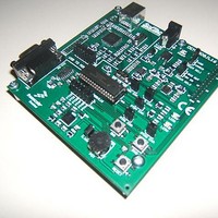
... The DEMO908JL16 Demonstration board has been designed for the evaluation, demonstration and the debugging of the Freescale MC68HC908JL16 microcontroller. The DEMO908JL16 can be used as a standalone application, or via its built-in USB-to-MON08 bridge, or together the Freescale Student Learning Kit (Freescale code: MCUSLK) through an external 28-pin I/O Header female connector. ...
Page 8
Introduction 1.5 Getting Technical Support Technical assistance is provided to all customers. For technical assistance, documentation and information about products and services, please refer to your local SofTec Microsystems partner. SofTec Microsystems offers its customers a technical support service at ...
Page 9
... Hardware Features 2.1 Demonstration Board Features The DEMO908JL16 board features MCU section containing: An MC68HC908JL16 microcontroller (in 32-pin SDIP package, already programmed with a demo application—in addition, you can also use any other pin- to-pin-compatible device); One clock sources: a 9.8304 MHz crystal, selectable via the “OSC ENA” jumper. ...
Page 10
... An RS-232 section providing one RS-232 channel connected to the microcontroller’s SCI serial communication interface. The microcontroller’s PTD6/TxD and PTD7/RxD lines are used by the RS-232 channel accelerometer section featuring a Freescale MMA7260Q sensor. All of the sensor’s input/output lines are connected to the microcontroller via jumpers. 7 Page The DEMO908JL16 Demonstration Board ...
Page 11
... A USB port; CD-ROM drive for installation. 3.3 Installing CodeWarrior Development Studio To install the CodeWarrior Development Studio Special Edition, insert the CodeWarrior CD- ROM into your computer’s CD-ROM drive. A startup window will automatically appear. Follow the on-screen instructions. DEMO908JL16 User's Manual Page 9 ...
Page 12
Software Setup 3.4 Installing SofTec Microsystems Additional Components The SofTec Microsystems Additional Components install all of the other required components to your hard drive. These components include: The Demonstration Board’s USB driver; The software plug-in for CodeWarrior; Examples; Demonstration Board’s ...
Page 13
... New Hardware Wizard” procedure, asking you to specify the driver to use for the instrument. On Windows XP (SP2) the following dialog box will appear. Select the “No, not this time” option and click the “Next >” button. 6. The following dialog box will appear. DEMO908JL16 User's Manual Page 11 ...
Page 14
Hardware Setup Click the “Next >” button. 7. Depending on your Windows settings, the following warning may appear. Note: this warning is related to the fact that the USB driver used by i the Demonstration Board is not digitally signed ...
Page 15
... Two jumpers (“POWER SEL1” and “POWER SEL2”) specify which power source to use. These two jumpers work together, as detailed in the table below. Care must be taken in setting these jumpers appropriately. Please refer to the following table for details. DEMO908JL16 User's Manual Page 13 ...
Page 16
Hardware Setup “POWER SEL1” “POWER SEL2” “USB” “3V3 OUT” “5V IN” Removed “UNREG” “3V3 OUT” “5V IN” Removed Removed “3V3 OUT” “5V IN” Removed Page 14 Configuration Selected Power supply taken from the USB connector. 3.3 V supplied to the ...
Page 17
... In host mode the program execution is controlled by the host PC through the “USB” connector. You can use the PC to debug the application by, for example, executing the program step by step and watching how the microcontroller registers vary, using the provided CodeWarrior Development Studio. DEMO908JL16 User's Manual Page 15 ...
Page 18
Operating Modes Note: all of the HC08 family devices feature a monitor code resident in i ROM which, through a serial communication line, allows the programming and the in-circuit debugging of the user application. The monitor code is executed in ...
Page 19
... From the CodeWarrior main menu, choose “File > Open”. Select the “Demo.mcp” workspace file that is located under the “\Program Files\SofTec Microsystems\ DEMO908JL16\CodeWarrior Examples\C\Demo” directory. Click “Open”. The Project Window will open. 5. The C code of this example is contained in the “main.c” file. Double click open it ...
Page 20
...
Page 21
... The SW1 push-button is connected to the microcontroller’s PTA1 input (default) Not Installed: The SW1 push-button is not connected to the microcontroller POTENTIOMETER ENABLE Installed: The potentiometer is connected to the microcontroller’s PTD3/ADC8 analog input (default) Not Installed: The potentiometer is not connected to the microcontroller DEMO908JL16 User's Manual Page 19 ...
Page 22
Summary of Jumper and Connector Settings Name Reference J202 J203 J204 1 J402 1 7.2 Connectors Name Reference J301 2 1 Page 20 Description/Pinout LED0 ENABLE Installed: The LED0 is connected to the PTD4 port of the microcontroller (default) Not ...
Page 23
... Name Reference J201 J401 Description/Pinout RS-232 Connector 1. N. N.C. 5. GND 6. N.C. 7. N.C. 8. N.C. 9. N.C. USB Connector USB Bus Power Supply Line 2. USB D- 3. USB D+ 4. GND DEMO908JL16 User's Manual Page 21 ...
Page 24
Summary of Jumper and Connector Settings Name Reference J103 Page 22 Description/Pinout ...
Page 25
... Name Reference J104 Description/Pinout MON08 Connector (Not Populated) 1. N.C. 2. VSS 3. N.C. 4. RST# 5. N.C. 6. IRQ# 7. N.C. 8. N.C. 9. N.C. 10. PTB0/ADC0 11. N.C. 12. PTB1/ADC1 13. OSC1 14. PTB2/ADC2 15. VDD 16. PTB3/ADC3 DEMO908JL16 User's Manual Page 23 ...
Page 26
...
Page 27
... Click the “Device Manager” button. 6. The “uDART In-Circuit Debugger” device will be shown with an exclamation mark next to it. Double click on this device the “General” tab, click the “Reinstall Driver” button. Follow the on-screen instructions. DEMO908JL16 User's Manual Page 25 ...
Page 28
...
Page 29
...
Page 30
...
Page 31
...
Page 32
...